Amplifier characterization using load pull

Load pull is a powerful method for characterizing RF power amplifiers through impedance variation. Load pull enables model extraction and validation as well as performance, ruggedness and efficiency testing.

Vector-receiver load pull application
Open Lightbox

Your task

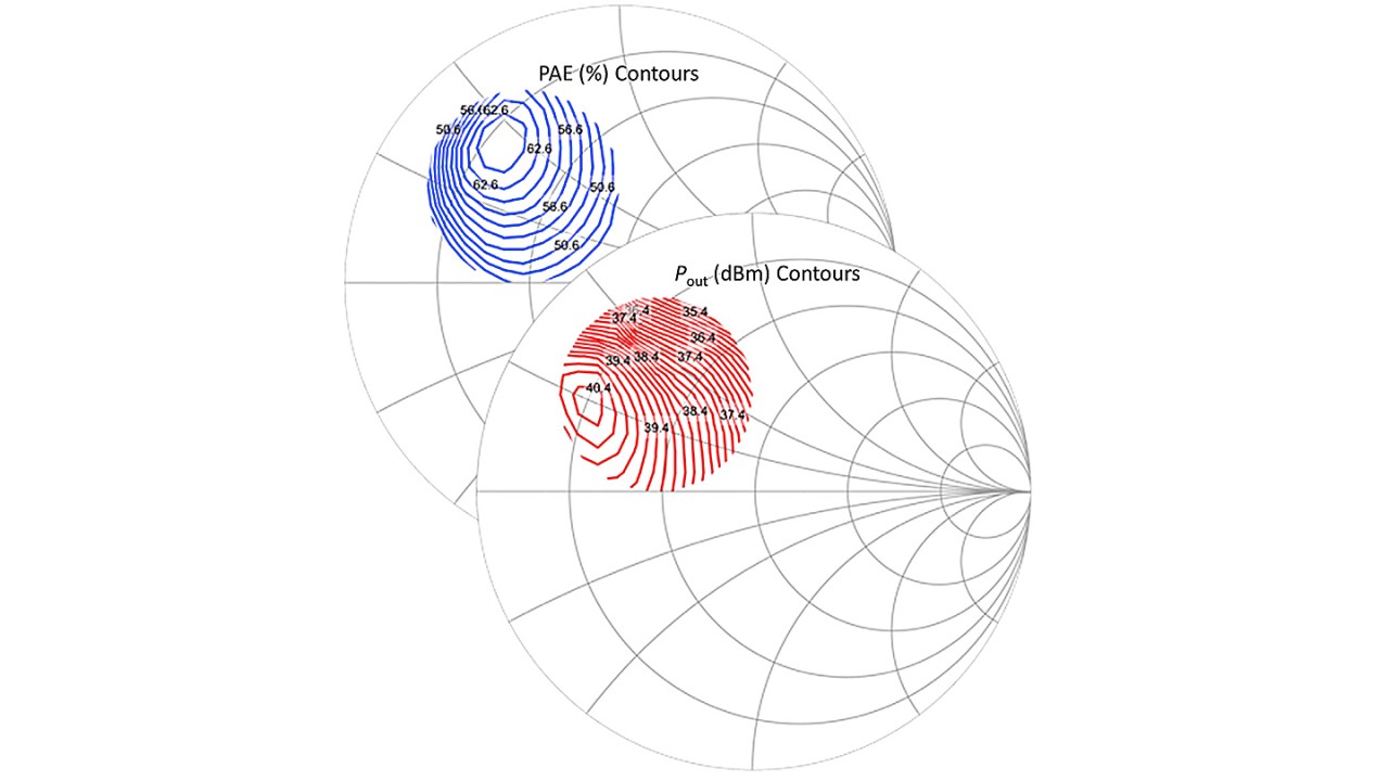
You are designing a power amplifier, which is not inherently a 50 Ω device. However, the target environment is typically a 50 Ω world, so an appropriate matching network is required. The performance of the amplifier is highly dependent on the load impedance. You characterize the amplifier using different source and load impedances and optimize it for gain, output power (Pout) and power added efficiency (PAE). This helps design a suitable matching network. Amplifiers typically operate close to compression for best efficiency. Classic small-signal S-parameters would not adequately describe the device under test (DUT). Instead, you need large-signal excitation and load impedances without 50 Ω matching to characterize the nonlinear behavior of the DUT. Vector wave quantities (a1, b1, a2, b2) describe the DUT behavior and allow amplifier model creation and validation.

Contours of power added efficiency (PAE) in % and output power (Pout) in dBm
Open Lightbox

T&M solution

Load pull relies on the flexible variation of the impedance acting on the amplifier. The main parameter to be modified during the measurement is neither frequency nor level or bias voltage, but the impedance presented to the DUT input and output at fundamental and harmonic frequencies. Load pull enables characterization of the DUT as a function of varying load impedances.

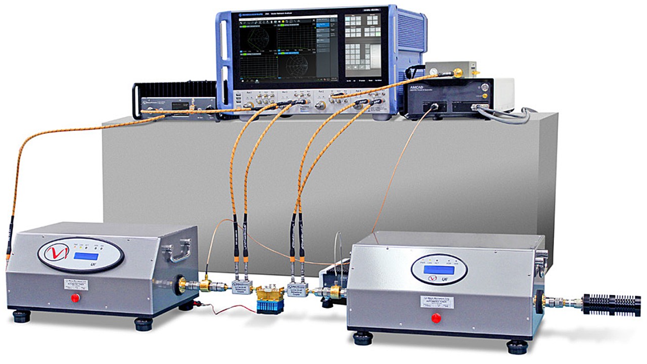
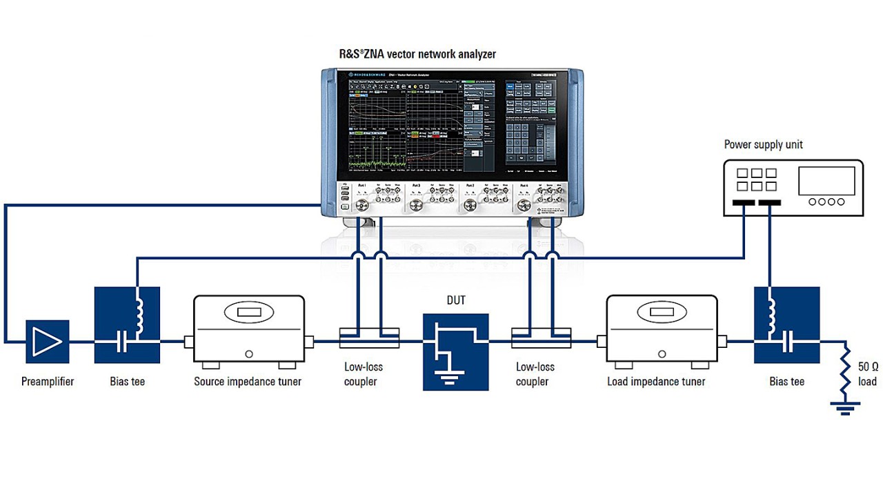
Load pull measurement setups today most commonly include a vector network analyzer (VNA) such as the R&S®ZNA, plus source and load impedance tuners. Direct receiver access on the VNA allows measuring the vectors of the a and b waves toward and from the DUT via external low-loss couplers. The VNA enables calibration at the DUT reference plane, ensuring maximum stability and accuracy for a and b wave quantity measurements.

Application

All parameter values of interest such as the reflection coefficients Γ on the input and output of the amplifier, input power, output power, gain, efficiency and power added efficiency can be derived from the measured wave quantities (amplitude and phase). The setup also enables a look into the tuners to accurately measure and control the respective impedances as presented to the DUT.

The setup can be easily enhanced to an active or hybrid load pull system or a combination of active and passive load pull. This extends the available tuning range at the DUT reference plane by injecting an additional, phase-coherent signal. It allows characterizing very low impedance devices over a wide range of impedances. This technique is also used if harmonic load pull is needed for enhanced device characterization and extracting complex DUT models.

Supported signal types often include CW and pulsed CW. Pulsed signals are essential for raw-die and on-wafer measurements to avoid temperature variations during the test due to self-heating of the device.

Rohde & Schwarz is collaborating with leading industry partners Focus Microwaves and Maury Microwave to offer turnkey load pull system solutions.

See also: www.rohde-schwarz.com/product/zna

Vector-receiver load pull measurement setup
Open Lightbox