Rohde & Schwarz solution
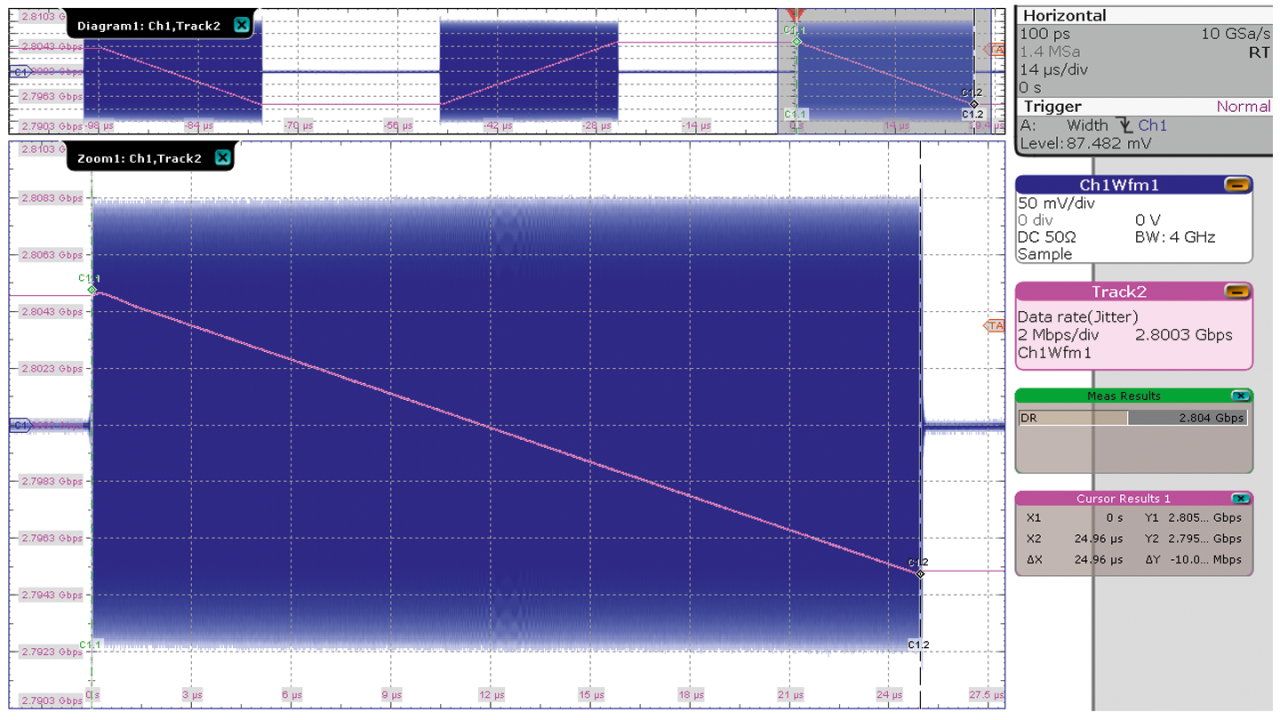
The R&S®RTO and R&S®RTP oscilloscopes can analyze RF pulses with frequencies up to 6 GHz/8 GHz. The most important feature for pulse analysis is the digital trigger. Compared to an analog trigger, the digital trigger has much better trigger sensitivity and no bandwidth limitation for an advanced trigger type. To analyze the RF pulse, the trigger must always appear in the same position relative to the pulse. As an example, a pulse train is used with a pulse duration of 25 μs and a PRI of 50 μs (see screenshot below). A zoom shows the third pulse in greater detail at the trigger position (t = 0 s).
For this acquisition, a width trigger is used. The trigger setup (Trigger on radar RF pulses with an oscilloscope - Application card, PD 3609.2000.92 Rohde & Schwarz GmbH & Co. KG) and envelope analysis (Analyzing RF radar pulses with an oscilloscope - Application card, PD 5215.4781.92, Rohde & Schwarz GmbH & Co. KG) are described in separate documents. The horizontal scale is set to 14 μs/div so that three pulses are captured to analyze the modulation sequence.
Now, the pulse is demodulated. The example pulse train is frequency modulated and is demodulated using one of the oscilloscope’s automated frequency measurements. Using this measurement together with the track functionality, frequency results are displayed as a function of time. This approach works well for wideband radar signals such as automotive radars. For narrowband signals such as ATC radars where the carrier frequency is large relative to the occupied bandwidth (fC >> fB), the track function looks quite noisy. This noise limits the accuracy of the chirp rate measurement and requires additional noise reduction.
The noise reduction of the signal is not straightforward. A simple bandpass filter cannot be used due to the changing carrier frequency. The filter bandwidth must be quite large. In a conventional, coherent radar system, the RX and TX paths share a stabilized local oscillator. For an oscilloscope, downconversion with the local TX oscillator is impossible because this signal is unavailable. Utilizing a phase locked loop (PLL) 1) to demodulate the signal is another approach.
1) Richard, Mark (2013): Fundamentals of Radar Signal Processing. 2. Edition: McGraw-Hill Companies
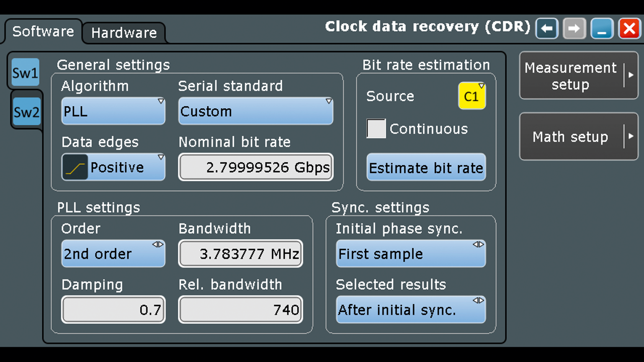
The R&S®RTO and R&S®RTP oscilloscopes have a software- based clock data recovery (CDR) that is equivalent to a PLL. Using the automated measurement function, the data rate essentially measures the instantaneous frequency of the pulse. When the track function of the data rate is turned on, the instantaneous frequency is displayed over time (see Track 2 on the right side of the first screenshot). Due to the use of the data rate function, the vertical unit of the displayed track is gigabit per second (Gbps), which is equivalent to GHz since the bit period and the sine period are the same.
Diagram 1 (upper section of the first screenshot) shows the modulation sequence of down-updown chirps within the pulse train of three pulses. For a more detailed analysis, the cursor on the track in the zoom window can be used to measure the chirp rate. This measures the frequency change of the pulse over time. For the given example, Cursor Results 1 (lower right of the first screenshot) shows 10 MHz in 25 μs for the down chirp.


