Trigger on radar RF pulses with an oscilloscope

Analyzing RF pulses is a key aspect of pulsed radar applications, e.g. in air traffic control (ATC), maritime radar or scientific measurements of the ionosphere. Analyzing the envelope and the modulation of the pulse is essential, because they contain important information to characterize the application. The R&S®RTO and R&S®RTP oscilloscopes are capable of triggering precisely on a pulse as a prerequisite for time domain and frequency domain analysis. This document describes the use of the R&S®RTO and R&S®RTP to trigger exactly on pulses in preparation for further in-depth measurements such as RF pulse measurements on an ATC signal.

Your task

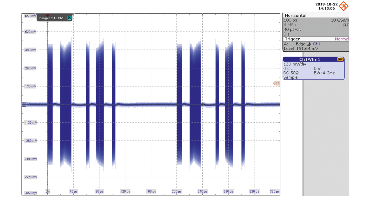
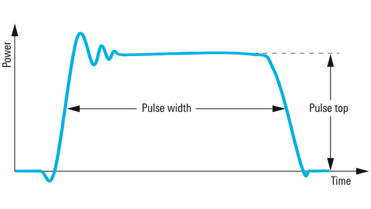
You have to measure radar RF pulses with respect to frequency, modulation, rise/fall time and pulse repetition interval (PRI), duration and amplitude to judge if they fulfill your requirements 1). So you need to trigger on a pulse in a reproducible manner to position the pulse correctly for the measurements and to efficiently store only pulses and not the pause. A conventional edge trigger will not create a stable display since a pulse typically contains multiple edges where a trigger can be positioned. In a complicated scenario (see screenshot below) where multiple pulses with different pulse widths (5.0/10.0/3.0/7.5/3.0 μs) and modulations are present, the edge trigger cannot be used.

1) Richard, Mark (2013): Fundamentals of Radar Signal Processing. 2. Edition: McGraw-Hill Companies

Sequence with multiple pulses

Rohde & Schwarz solution

The R&S®RTO and R&S®RTP oscilloscopes can analyze RF pulses with frequencies up to 6 GHz/8 GHz. The most important feature for pulse analysis is the precision digital trigger. Compared to an analog trigger, the digital trigger has much better trigger sensitivity and no bandwidth limitation for an advanced type of trigger. To analyze the RF pulse, the trigger must always appear in the same position relative to the pulse. As an example, a pulse train is used to set up a trigger specifically on the 7.5 μs pulse (circled in red) with a power level of 5.0 dBm (= 400 mV) and a carrier frequency fC of 2.8 GHz.

For this acquisition, an A-B-R trigger is used. While the pulse start triggers condition A, the B trigger is released by the end of the pulse after the specified pulse duration. The R trigger is then used to reset the condition for pulses that have either a too long pulse duration or a too high pulse power.

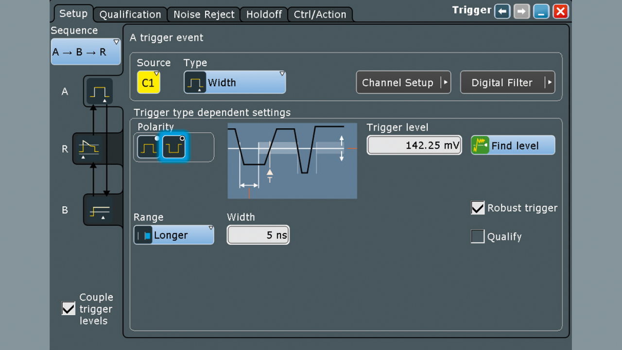
A trigger setup for the start of the pulse

A trigger

The A trigger uses the trigger type “Width” with negative polarity. This trigger focuses on the pause between two consecutive pulses. The width should be larger than a few periods of the carrier (360 ps), in this example 5 ns. The level is set to the minimum accepted power level of –3.9 dBm (= 142.25 mV). Since the width trigger triggers on the radar pulse, the robust trigger option should be enabled (see screenshot below). This setting is sufficient for an A trigger for stable triggering on the start of every pulse.

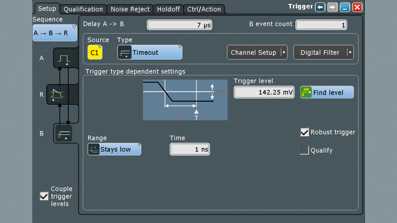
B trigger setup up for the end of the pulse

B trigger

The B trigger (see following screenshot) uses the trigger type “Timeout” with the same power level as the A trigger. Coupled trigger levels are used. Analog to the A trigger, the timeout time should be larger than a few periods of the carrier (360 ps), in this example 1 ns.

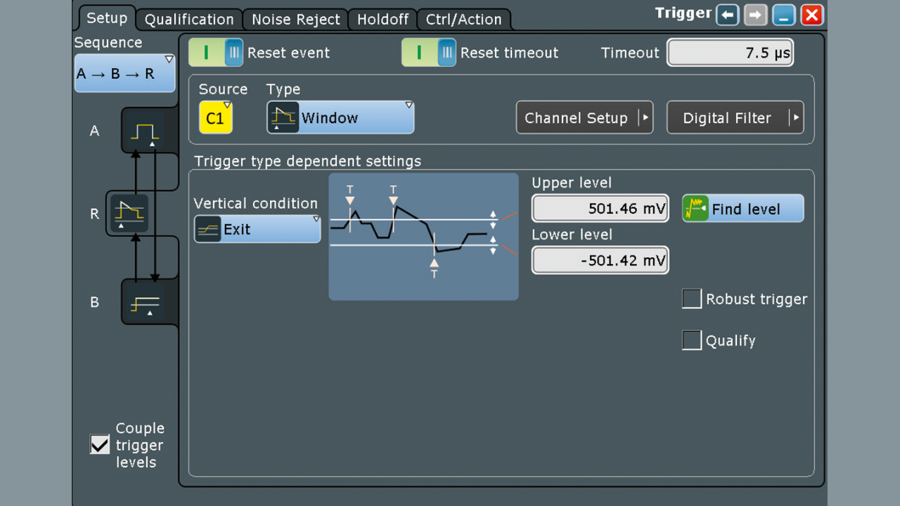
R trigger setup up to reset the trigger condition

R trigger

Pulses that are longer than 7.5 μs or exceed 10 dBm should be discarded. This is accomplished by applying the R trigger (see screenshot below). This resets the A trigger condition. Enabling the reset timeout and setting the timeout to the maximal allowed pulse length (7.5 μs) will discard longer pulses. Pulses with higher pulse power will be ignored due to the window trigger. Therefore, the type is set to “Window” with the vertical condition “Exit”. The levels are set symmetrical to 7.0 dBm (= 501.46 mV).

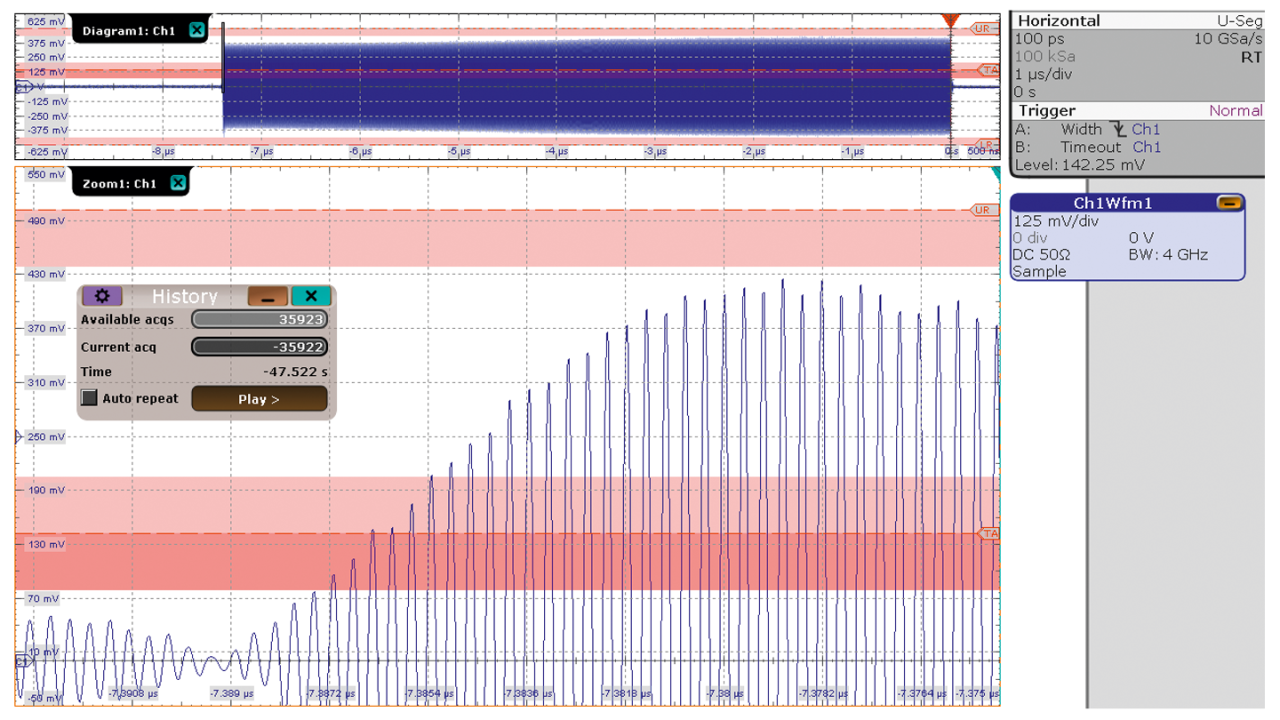
As a result, pulses with a pulse duration between 7.0 μs and 7.5 μs and a power level between –3.9 dBm and 7.0 dBm are acquired out of a sequence of different pulses. These pulses are stored with a low percentage of offtime always in the same trigger position at the end of the frame (indicated by the red triangle in Diagram 1 in the upper section of the screenshot below).

In this example, the R&S®RTO equipped with 1 Gsample memory size can store about 36 000 consecutives pulses. The history mode allows access to all acquisitions for a detailed analysis of each pulse as well as pulse-to-pulse analysis.

Parameter translation

The table gives an overview how the pulse parameters translate into oscilloscope trigger parameters:

Parameter translation
Pulse parameter Oscilloscope parameter
Pulse top (min.) (A) trigger level
Pulse top (max.) (R) exit upper/lower level
Pulse width (min.) (B) delay A ▷ B
Pulse width (max.) (R) timeout

Summary

The R&S®RTO and R&S®RTP oscilloscopes analyze RF pulses to the maximum bandwidth of the model used. To perform detailed analysis, the R&S®RTO and the R&S®RTP trigger precisely on pulse characteristics such as pulse width and power level, similar to an IF power trigger in spectrum analysis. The digital trigger works to the full bandwidth and is a key feature. Once the pulse is acquired, the R&S®RTO and R&S®RTP allow accurate characterization of envelope 2) and modulation since the pulse is well positioned within the acquisition. Pulse-to-pulse analysis on consecutive pulses is also possible.
2) Analyzing RF radar pulses with an oscilloscope (Application card, PD 5215.4781.92, Rohde & Schwarz GmbH & Co. KG).

Captured 7.5 μs pulse using the A-B-R trigger