Intelligent modeling of sequences with pulses and waveform segments

The R&S®Pulse Sequencer software offers a powerful mechanism to model sequences that are often required for meaningful radar receiver test cases. The sequences can consist of many individual elements, such as pulses defined by the software or imported waveform segments. The software’s powerful interpulse modulation mechanism gives the user full control of each single element.

Your task

Radar engineers often have to create realistic arbitrary sequences of signals quickly, reliably and repeatably in the lab to verify the performance of components as precisely as possible. These sequences commonly contain many modulated or unmodulated pulses with fixed parameters such as pulse width (PW), pulse repetition interval (PRI) or pulse top power level. For agile signals, pulse parameters vary from pulse to pulse. Therefore, engineers normally use interpulse modulation (IPM) profiles to define those signals. In addition, engineers want to use recorded waveform segments in a sequence, combine them with defined pulses or apply IPM profiles to them.

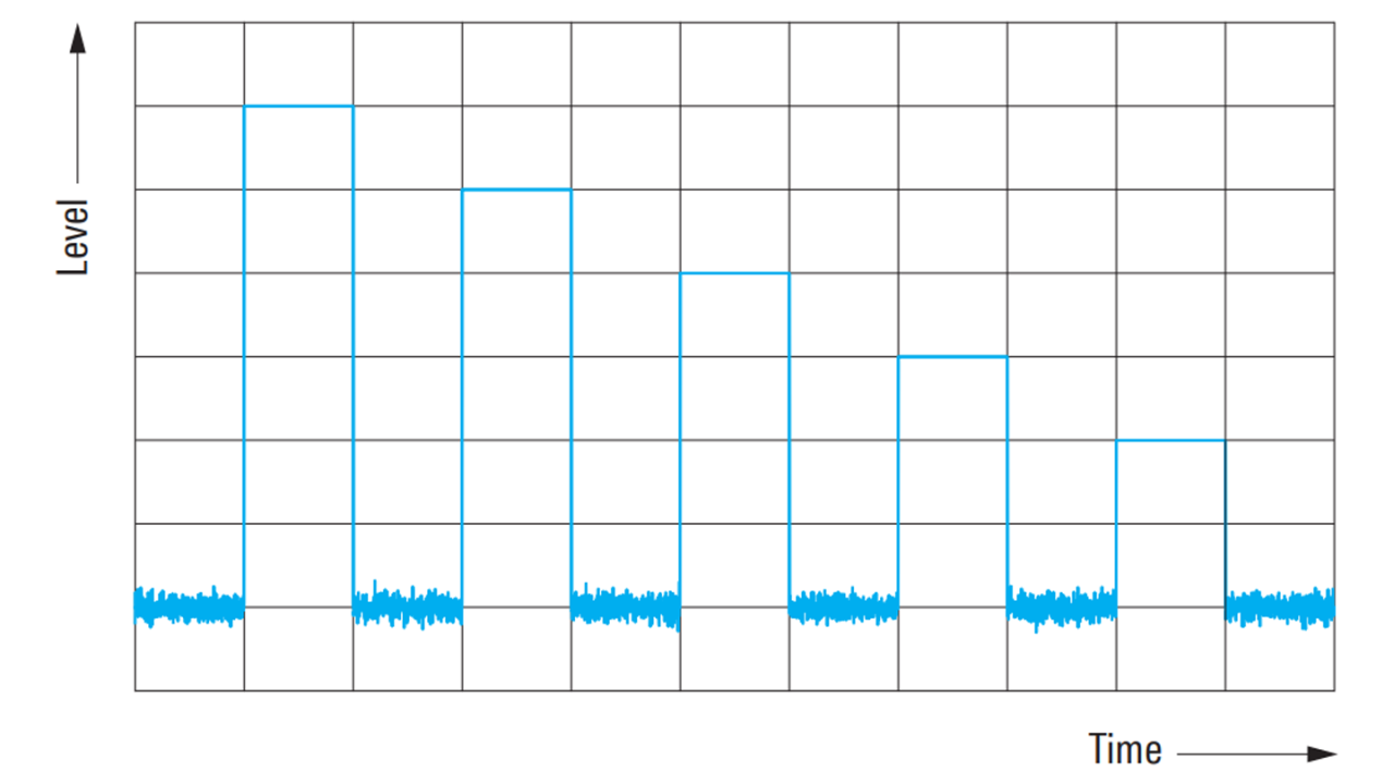
Sequence of pulses with level offsets

T&M solution

The R&S®Pulse Sequencer software together with any Rohde & Schwarz vector signal generator (R&S®SMW200A, R&S®SMBV100A or R&S®SGT100A) equipped with the K300 pulse sequencing option or the K301 enhanced pulse sequencing option perfectly fulfills all needs. The R&S®Pulse Sequencer software enables users to define a variable amount of pulses or to import waveform segments. Both can be used repeatably or embedded within loops or nested loops to model sequences as arbitrary and complex as desired. Offsets of frequency, amplitude, phase and time delay can be individually defined for each pulse or waveform segment. For agile signals, interpulse modulation profiles can be defined in the software and applied to the individual elements of the sequence. Superposition of signals, such as two interfering pulses, can also be modelled. The software calculates the resulting signal if two overlaying signals are defined in the sequence.

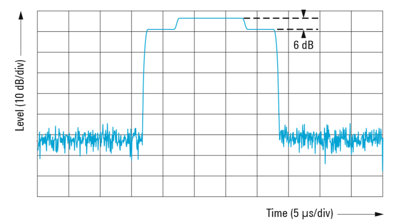
Superimposed unmodulated pulses with different pulse widths coherently overlayed in phase
Open Lightbox

Superimposed interfering pulses

In a crowded radio spectrum with a high pulse density, radar receivers and components need to work properly where radar signals overlay in time, for example in the case of interfering pulses from different emitters. Modern receivers must also be able to recognize the individual radar pulses when they overlay and interfere with each other. The R&S®Pulse Sequencer software enables radar engineers to model these test cases of interfering radar pulses by using the integrated “overlay” feature when configuring a sequence.

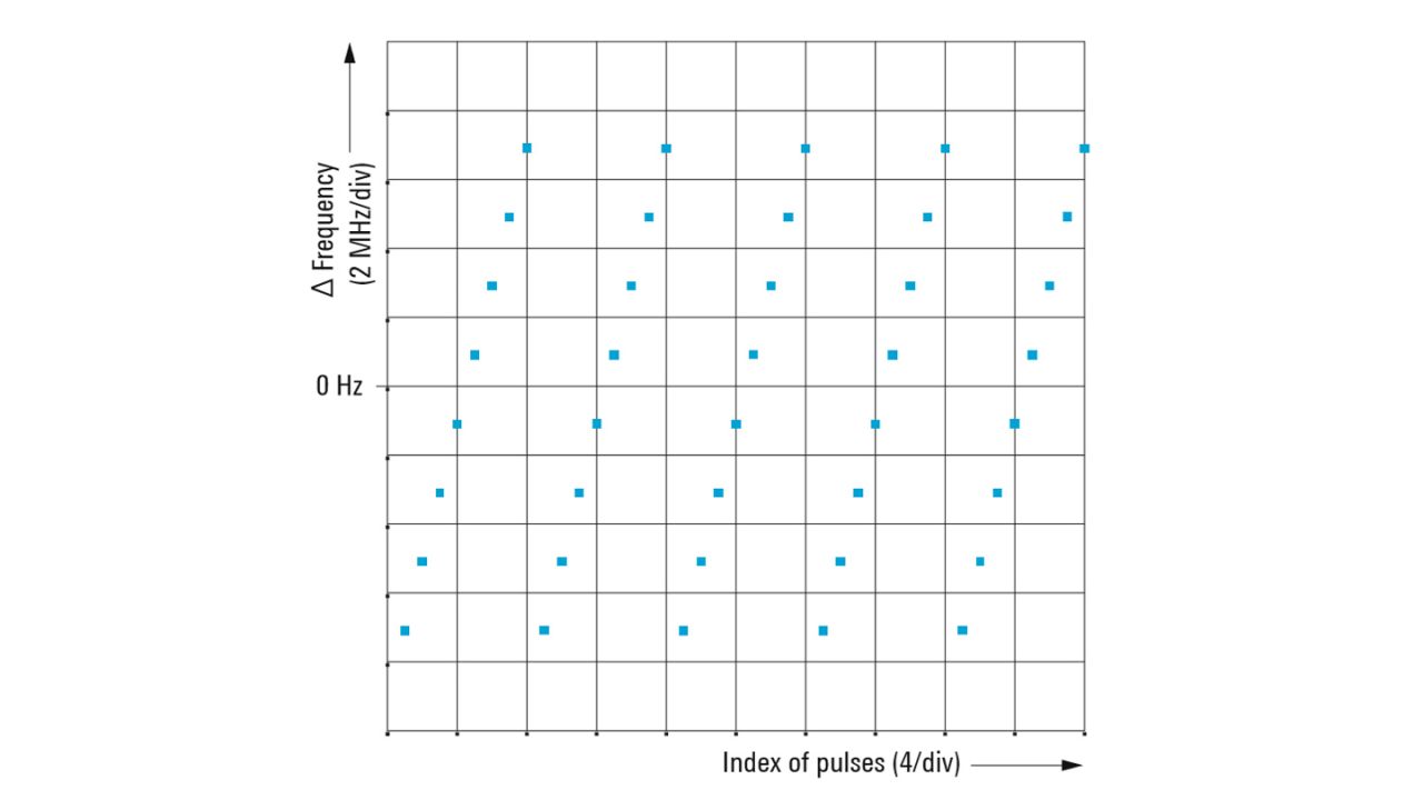
Interpulse modulation: frequency hopping
Open Lightbox

Frequency hopping

Radar systems often use frequency agility techniques such as frequency hopping to avoid interference with other radar systems or jamming. Radar warning receivers must be tested in these frequency hopping scenarios. The bottom left figure shows a typical frequency hopping scenario. In this scenario, the transmit frequency is shifted by 2 MHz from pulse to pulse, from –7 MHz up to 7 MHz around the RF frequency. With the wideband baseband of the R&S®SMW200A vector signal generator, an offset up to ±1 GHz can be simulated.

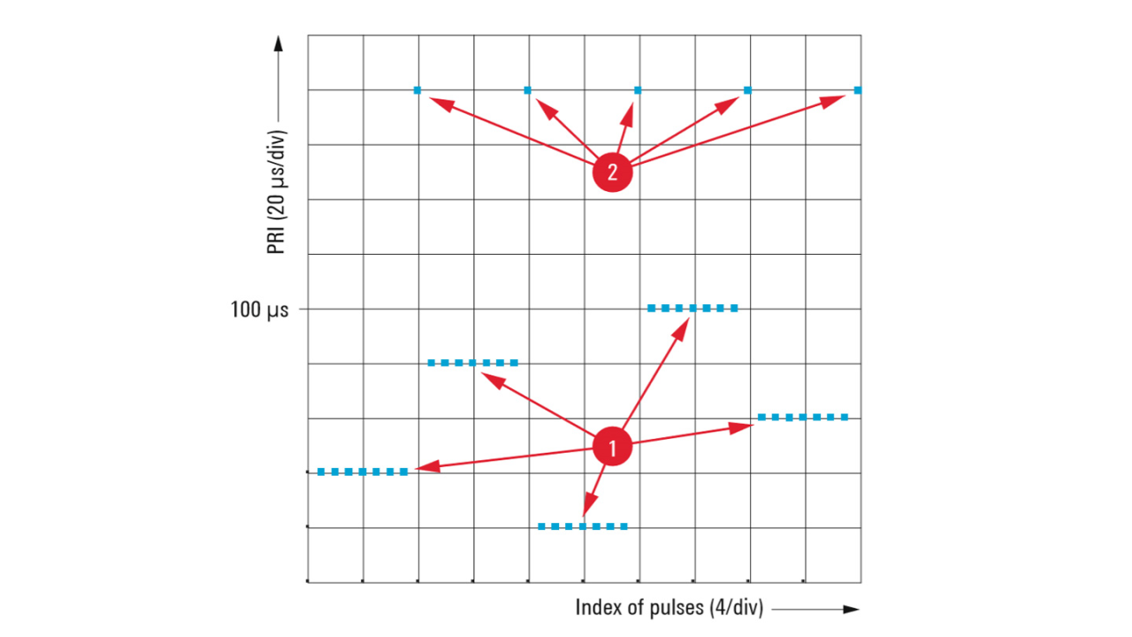
Interpulse modulation: PRI staggering
Open Lightbox

PRI staggering

Modern radar systems often vary the PRI from burst to burst, e.g. to resolve range and Doppler ambiguities. The bottom right figure shows a typical PRI staggering scenario. Here, a burst contains a group of seven pulses (1) varying the PRI between 20 μs and 100 μs from burst to burst.

Through the flexibility of the R&S®Pulse Sequencer software, the PRI can also be controlled from pulse to pulse. In addition, an increased PRI (2) can be simulated together with the typical “PRI staggering” scenario. This is a good mechanism to model frequency-switching times of real radars if they use a new RF frequency for every burst. The R&S®Pulse Sequencer software supports these features with the integrated interpulse modulation profiles. All common pulse parameters such as timing, level and frequency are definable by the IPMs and can be controlled by deterministic profiles or random distribution profiles.

Multiple IPM profiles such as frequency hopping and PRI staggering can be used simultaneously. Furthermore, marker signals are definable to provide e.g. a source for triggering once at the start of a scenario or repeatedly for every pulse or waveform segment.

Key benefits

  • Enables quick and simple modeling of arbitrary sequences
  • Supports ARB-based signal generation or realtime sequencing via a sequencing list containing control words with the R&S®SMW-K501/R&S®K502 options
  • Provides advanced pulse and waveform segment sequencing
  • Implements loops, nested loops and overlays within a sequence
  • Supports all common interpulse modulations with deterministic profiles and random distribution profiles
  • Provides up to four marker signals