Air navigation ILS system’s antenna alignment using the R&S®ZNH

In civil aviation, instrument landing system (ILS) transmitters use antenna arrays to provide guidance to approaching aircraft. ILS performance strongly depends on the precise alignment of the magnitude and phase of each element in an antenna array. The R&S®ZNH handheld vector network analyzer with a built-in source allows fast, convenient on-site measurements on the ILS antenna system.

Air navigation ILS system

Your task

Instrument landing systems use antenna arrays to steer the transmitted beam in the desired direction. Precise information on the phase and magnitude of the antenna elements is essential to transmit the beam at the desired angle, providing correct navigation information to the aircraft. Any defects in the system components, e.g. the antenna cables or other components, will cause phase misalignment between the antenna elements. Engineers verify phase alignment during maintenance and align replaced components. A portable vector network analyzer is the most appropriate tool to determine phase misalignment.

Rohde & Schwarz solution

The R&S®ZNH handheld vector network analyzer with the R&S®ZNH‑K45 vector voltmeter option is the ideal tool for engineers to measure the absolute phase response of components in the antenna system and to verify the phase alignment between the antenna elements. The R&S®ZNH delivers highly accurate measurements of the absolute and relative phase and magnitude. The analyzer includes a signal source, bidirectional couplers and four independent receivers. Together with 1-port or full 2-port calibration routines, phase alignment is very convenient for engineers performing maintenance on ILS antenna systems.

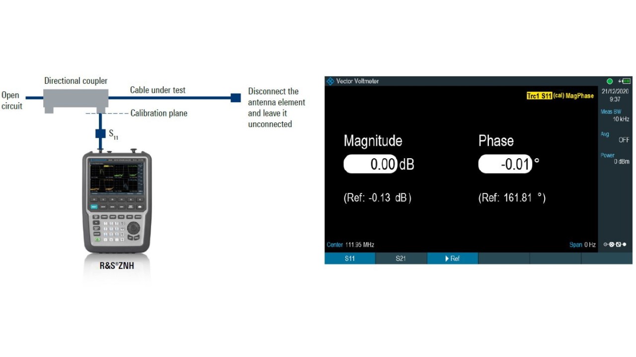
Fig. 1: Relative S11 reflection measurement between cables using 1-port setup
Open Lightbox

Application

Alignment of ILS antenna arrays can be performed using an R&S®ZNH with the R&S®ZNH‑K45 vector voltmeter option. Depending on the required application, a 1-port or 2-port setup should be used.

1-port setup

This setup is typically used to inspect the electrical length of the cables installed in the antenna array. Each cable in the corresponding element path must have equivalent electrical length. Any misalignment will result in a deviation of the generated beam from the desired angle. Engineers utilize such a setup when making maintenance checks since minimum disruption to the system is required. Perform a full 1-port calibration with the R&S®ZNH. For this, connect a calibration device to the directional coupler at the cable end (calibration plane). Disconnect the cable under test from the first antenna element and make an S11 reflection measurement to determine the cable’s magnitude and phase (see Fig. 1). When results are within specifications, set the measured values as reference values using the “►Ref” button. The normalized values for the magnitude and phase close to zero are displayed. Repeat the S11 measurement for the remaining cables. For the second and all subsequent cables, the relative magnitude and phase against the reference values are measured. Check if the measured values are within the desired tolerance.

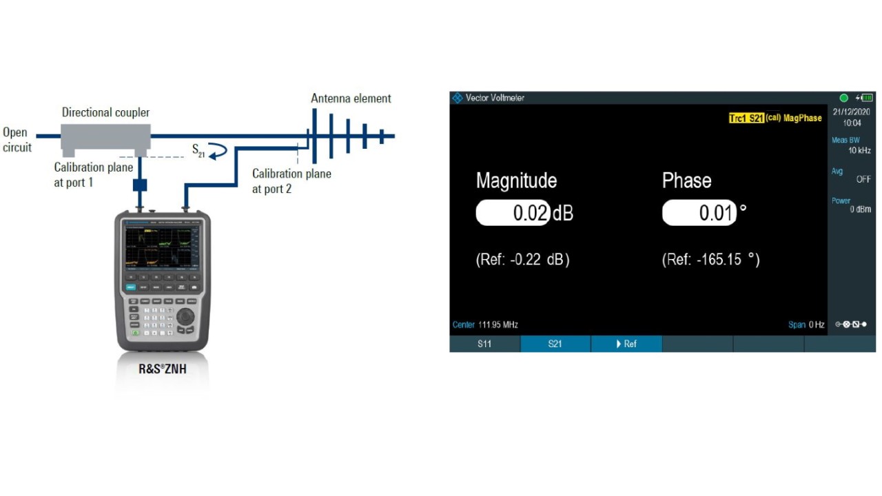
Fig. 2: Relative S21 transmission measurement between antenna elements using 2-port setup
Open Lightbox

2-port setup

This setup is used to test the magnitude and phase alignment for each element of the antenna array. Perform a 2-port TOSM or UOSM calibration using a calibration kit. Connect port 1 to the directional coupler arm and port 2 to the monitor port of the first antenna element. The calibration plane for each port is shown in Fig. 2. Perform an S21 transmission measurement on this antenna element and, if results are within specifications, set the measured values as reference values using the “►Ref” button. For all subsequent antenna elements, measure the relative S21 magnitude and phase against the reference values. The normalized magnitude and phase are displayed. Magnitude and phase misalignments between any antenna elements are determined, and adjustments are performed until the relative magnitude and phase are within desired tolerance limits.

Summary

For engineers in the ILS field, determining magnitude and phase misalignment between cables and antenna elements is no longer a tedious task using the R&S®ZNH handheld vector network analyzer. The R&S®ZNH in combination with the R&S®ZNH-K45 vector voltmeter option is the perfect tool for any antenna array measurements.

Related solutions