Cable impedance measurement

Interested?

R&S®Essentials | Spectrum and vector network analyzers fundamentals

Cable impedance measurement

Author: Paul Denisowski, Product Management Engineer

Measuring the characteristic impedance of coaxial cables is essential in high frequency electronics and telecommunications. This can be done using a vector network analyzer (VNA) and a Smith chart.

Coaxial cable impedance

A coaxial cable, commonly referred to as “coax,” consists of three main components:

  • Inner conductor: The central wire that carries the signal.
  • Dielectric insulator: A layer of insulating material surrounding the inner conductor.
  • Conducting outer shield: A metallic shield that encases the dielectric layer and serves as a return path for the signal as well as protection against external electromagnetic interference.

These parts are usually covered by an additional layer of plastic insulation. The characteristic impedance of a coaxial cable is a function of the inner and outer conductor diameters and the dielectric constant of the insulating material between them. Most coaxial cables are designed with characteristic impedances of either 50 or 75 Ohm. The impedance is often printed on the cable's outer jacket, but when this information is missing, a VNA can be used to measure it.

Coaxial cable structure

Using a VNA to measure characteristic impedance of coaxial cable

A VNA can measure the characteristic impedance of a coaxial cable using the quarter-wave impedance transformer principle. A quarter-wave impedance transformer is a transmission line that is one-quarter wavelength long and terminated in a known impedance, ZL. The characteristic impedance, Z0, can be calculated from the known value of ZL and the input impedance, Zin, measured with the VNA.

Characteristic impedance of coaxial cable

The measurement process can be broken down into four steps:

  • Calibration of the VNA: Perform an open-short-match (OSM) calibration on the VNA. While this step can enhance accuracy, it may not be necessary if the goal is simply to determine whether the cable impedance is 50 or 75 Ohm.
  • Connecting the cable: Attach the coaxial cable to the VNA and terminate it with a 50-Ohm load.
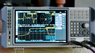
  • Running an S11 measurement: Configure and execute a reflection (S11) measurement on the VNA. The start and stop frequencies of the sweep must be set appropriately.
  • Interpreting the results with the Smith chart: Plot the measurement results on a Smith chart to determine the impedance. If both the cable and load impedance are 50 Ohm, the Smith chart will display a dot or a small circle in the center. If the cable and load impedances differ, the trace will form partial or multiple circles.

Cable impedance measurement process

Setting the correct sweep frequencies

The sweep frequencies must be properly configured to accurately measure the impedance:

  • The start frequency should be low, typically 100 kHz or lower.
  • The stop frequency should be set high enough for the trace to cross the resistive axis exactly once. An ideal stop frequency (in MHz) can be estimated by dividing 75 by the approximate cable length (in meters). This estimation is based on the quarter wavelength of the signal's speed in the cable.

Due to the slower propagation speed of signals in cables compared to a vacuum, the calculated stop frequency might cause a slight overshoot on the Smith chart. However, this can still yield acceptable results.

Finding correct sweep frequencies with Smith chart

Determining cable impedance

Once an “ideal” trace is obtained, use a marker to find the point where the trace crosses the resistive axis. This value represents the input impedance, Zin. Even if a trace point does not fall precisely on the resistive axis, using the closest point can still provide accurate results. Finally, calculate the characteristic impedance of the cable using the measured value of Zin and the known load impedance, ZL.

Summary

  • Most coaxial cables have a nominal impedance of 50 or 75 Ohm.
  • The impedance is often printed on the cable's outer jacket.
  • The impedances can also be measured using a VNA and the Smith chart.
    • Perform a standard one-port OSM calibration.
    • Attach the cable to the VNA and terminate it with a 50-Ohm load.
    • Run an S11 measurement with appropriately configured start and stop frequencies.
    • Interpret the results using a Smith chart. If the trace is near the center, the impedance is 50 Ohm; otherwise, find the point where the trace crosses the resistive axis.
    • Use the measured impedance, Zin, and the known load impedance, ZL, to calculate the characteristic impedance.
  • This methodology is also applicable to some types of cables other than coaxial.

Need more help with cable impedance measurements? Our experts will help you.

Related content

Curious to learn more about test fundamentals?

Sign up for our newsletter