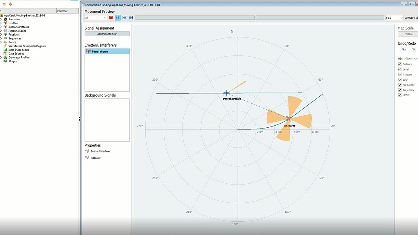
Simulation of receive power level


The flight path of the receiver (slowly moving red aircraft below) was imported from a trajectory simulator. The flight path is defined as waypoint file that includes location and attitude information with timestamps. The flight path of the emitter (blue patrol aircraft) uses a predefined trajectory provided by the R&S®Pulse Sequencer software. In this scenario, it is assumed that the radar of the blue emitter aircraft operates in the X-band and uses a pencil beam together with a raster scan. The light blue shaded area shows the sector that is covered by the raster scan. The scan rate is 30°/s (raster width 90°). The red aircraft carries radar warning equipment with 360° azimuthal coverage as part of its electronic support measure (ESM) system. It uses four sector antennas with cardioid antenna patterns.