Creating your own “smart” low-noise amplifier
Compensating external components using their S-parameters and R&S®FSW-K544

Compensating external components using their S-parameters and R&S®FSW-K544


In many applications, customized components are connected to the measuring instrument (e.g. a signal analyzer) to adapt it perfectly to a specific measurement task. Typical examples are cables (very long ones to connect a distant DUT), filters (to block strong signal components that limit the sensitivity of the measurement) and low-noise amplifiers (LNA) that boost the sensitivity of the measuring equipment. Most of these components reside within advanced signal and spectrum analyzers or can be ordered and integrated as optional hardware (e.g. an LNA, also called preamplifier).
Integrated components, however, are always a tradeoff. For an LNA, you have to trade off bandwidth, gain, noise figure and matching. Obviously, a trade-off is never a perfect fit for one specific application. Therefore, to measure the noise figure of a leading-edge amplifier, you may need an additional LNA to increase the instrument’s sensitivity. In contrast to a built-in LNA, very high gain and perfect matching may be required, but only in a very small frequency range, e.g. from 1.5 GHz to 2 GHz, whereas built-in components typically cover the entire frequency range of the instrument, e.g. from 2 Hz all the way up to 67 GHz or more.


Noise figure measurement setup with an additional, application-specific LNA
Rohde & Schwarz recommends finding the external component that perfectly suits your application and adding it to the measurement setup. With an additional component in the measurement, you must make sure that the measurement result characterizes the DUT, but not the component. So how can you compensate for the influence of this external component, i.e. its gain and frequency response?
The R&S®FSW signal and spectrum analyzer as well as many other Rohde & Schwarz instruments and software packages (e.g. R&S®VSE vector signal explorer software) offer user-defined frequency response correction (R&S®FSW-K544 option on the R&S®FSW). This option applies a filter that compensates for any given frequency response, including constant gain or loss.
In this example with an external LNA, measure the S‑parameters of this device using a vector network analyzer (VNA), making sure the LNA operates in its linear range, and export the data into a Touchstone file. Import the Touchstone file (e.g. s2p format) into the R&S®FSW-K544 option and apply the correction. Your measurement results displayed on e.g. the R&S®FSW will appear as if the external LNA were a component integrated into the R&S®FSW.
Even daisy-chaining of components is possible. The R&S®FSW-K544 software option will combine the S‑parameter
matrices of multiple components or even the input/output matching of the instrument and the DUT, if required. To integrate your LNA or component into the measurement setup and fully compensate for its frequency response, perform the following:
Step 1: Measure the component on a VNA, and export a Touchstone file containing the two-port S-parameters.
Step 2: Import the Touchstone file into R&S®FSW-K544, and activate the user-defined frequency response correction.
Step 3: Measure your DUT with any of the R&S®FSW measurement applications, with your components fully compensated.
The user-defined frequency response correction allows you to make all your components “smart” by simply providing their S-parameters.


Characterization and compensation of the additional LNA


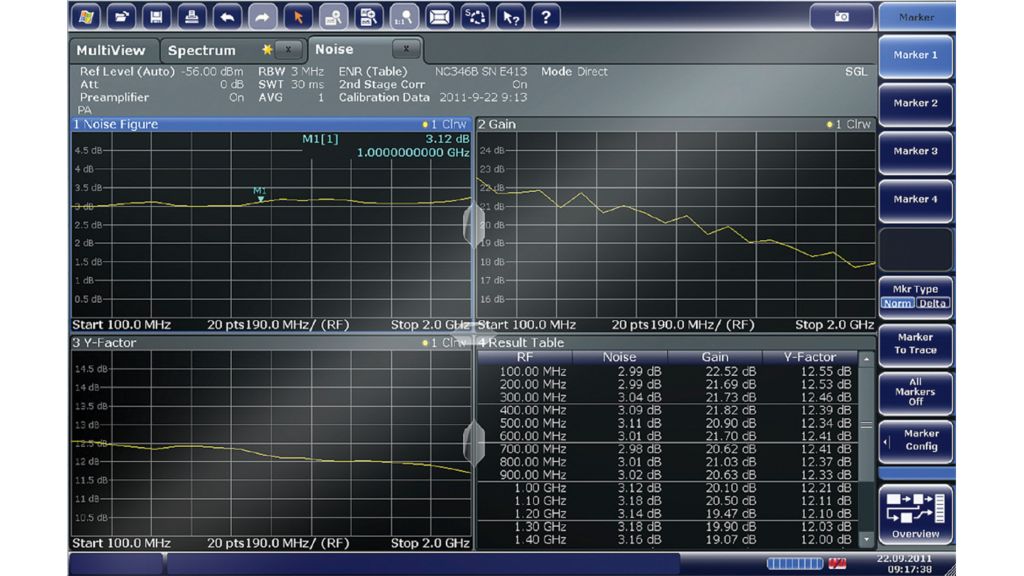
Measurement results