Revolutionized pulsed signal generation: easy, intuitive, powerful

The R&S®Pulse Sequencer software together with any Rohde & Schwarz vector signal generator offers an easy and convenient way to generate pulses. For the first time, one package helps you define all the test cases you need in the lab for your entire product development cycle. Test cases extend from simple pulse scenarios for initial component testing to complex 3D radar emitters for acceptance testing of complete systems.

Your task

Radar engineers often have to use many different software tools, some of which may even be obsolete, to define pulsed signals. Creating such signals usually takes a lot of programming effort – time that is better spent testing and improving the product. Time and cost reduction are significant goals in the development process.

T&M solution

With the R&S®Pulse Sequencer software, engineers now have a single software tool to define pulsed signals for different levels of complexity. It offers features for receiver tests in every stage of the design process:

  • Single sequences or a collection of sequences with pulses and waveform segments
  • Emitters or a collection of emitters with antenna diagrams and scans
  • 3D map-based scenarios with emitters
  • Direction fi nding scenarios for multichannel receivers

Single sequences with R&S®Pulse Sequencer

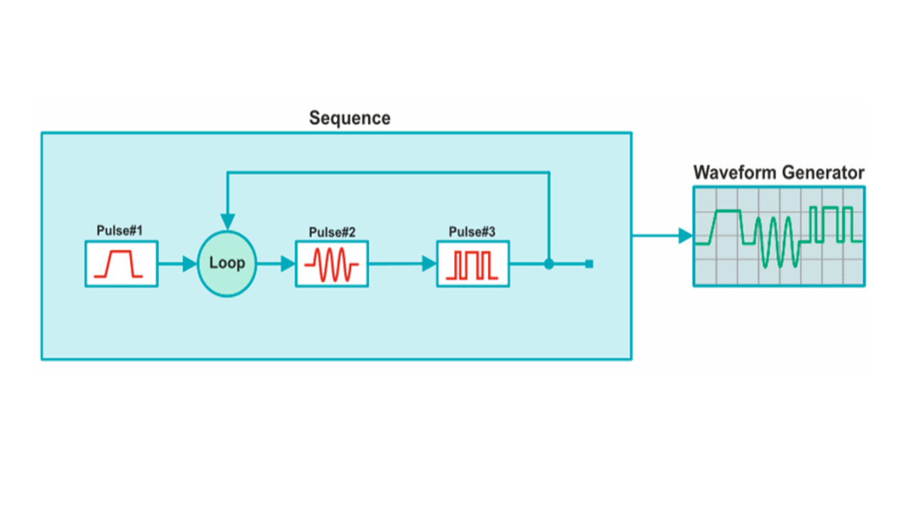
The simplest test case is a single pulse, which is created by defining its shape and the pulse pause and embedding it into a single sequence. This is perfect for component testing if only a few pulses with precise pulse shape are needed, e.g. to simulate real-world parasitic effects such as overshoots.

The complexity can easily be increased by using loops, nested loops and overlays. Overlays allow you to create e.g. interfering and overlapping pulses. Interpulse modulation (IPM) is a powerful mechanism for varying the parameters (amplitude, phase, offset frequency) within a pulse sequence from pulse to pulse by using profiles such as predefined deterministic or random lists, steps, equations or customer-defined plug-ins. IPM is perfect for modeling frequency hopping, PRI stagger, pulse width variation, etc. IPM works on configured pulses and on imported user-defined waveform segments. Markers can be added directly in the sequence, e.g. as a trigger source for the analyzer or other DUTs. These markers can be set to the rising or falling edge, pulse width, etc. The settings are automatically transferred to the signal generator as previously configured in the software.

Single sequences
Single sequences
Open Lightbox

The signal can be configured in the software as a classical waveform (ARB), as a multisegment waveform (MSW) where the sequence is preprocessed and split up into sequential segments to save memory, or as a sequence list of control words (with the R&S®SMW-K501/-K502 extended sequencing options).

Several single sequences can be combined to form a collection of sequences, where you can switch between individual sequences and select the one to be played. All sequences are instantly calculated and each sequence can be played immediately after it is selected.

Single emitter with R&S®Pulse Sequencer

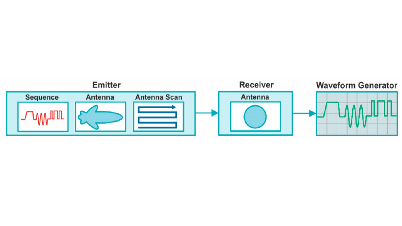
The single emitter scenario is used to combine the effects of antenna-specific parameters (patterns, scans, gain) with a sequence. This makes it possible to test receivers against pulses whose amplitudes over time are defined by a scanning antenna. It provides the most realistic modeling of real-world scenarios. The benefits of the R&S®SMW-K501/K502 options can best be seen when long antenna scans have to be modeled.

Single emitter
Single emitter
Open Lightbox

The options define the signal based on a sequence list of control words that refer to defined pulses or precalculated waveform segments. This approach allows a long signal playtime of several hours with minimum required memory.

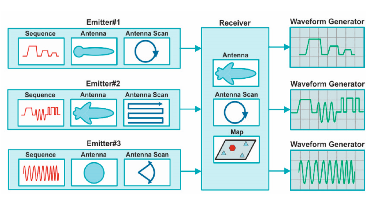
Several emitter signals can be combined to form a collection of emitters. You can choose different emitter signals with individual sequences, antenna parameters or scans – without additional precalculation. The R&S®Pulse Sequencer software creates output signals as an ARB waveform, a multisegment waveform or as a sequence list of control words (with the R&S®SMW-K501/-K502 extended sequencing options) – a very easy way to bring reality into your lab.

Localized emitters

Emitters can also be localized on a map to simulate 3D scenarios. They can be dragged and dropped to the desired position on the map, and their coordinates, the attitude (yaw, pitch, roll) and height can be adjusted by entering the respective values. In a single emitter scenario, the receiver antenna is modeled as omnidirectional. In a localized emitter scenario, however, receiver-specific antenna parameters (gain, pattern, scan type, etc.) are available and the receiver attitude can be configured. The software calculates the signal as it would occur at the receiver antenna output. The resulting signal includes all contributions from the emitter and receiver, such as distance, scanning antennas, antenna polarization, attitude, etc. Background emitters can be used together with a wanted emitter. They embed a wanted emitter into noise-like emitters.

Localized emitter scenario
Open Lightbox

You define the number of background emitters and their parameters such as PRI range, pulse duration range and frequency range. For each background emitter, the parameters are randomly selected from within the user-defined range. In addition, telecom interferers can be used in the simulation to model realistic coexistence tests. These unique features allow you to conveniently create scenarios with both pulsed signals and any I/Q modulated interfering signal, or with background emitter signals with high pulse density. Expensive field tests become obsolete.

Direction finding with R&S®Pulse Sequencer

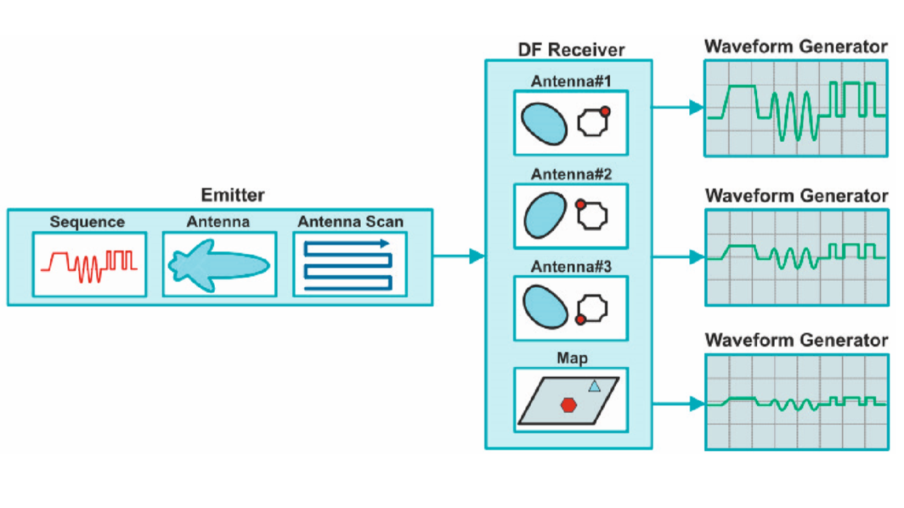
The R&S®Pulse Sequencer software also simulates signals with different angles of arrival (AoA). This is needed to test the performance of multichannel receivers. In the direction finding scenario, the emitters and the required multichannel receiver antennas can be configured on the 3D map. For each receiver input, the correct signal is calculated in consideration of the relative positions of the emitter and the receiver antennas and their properties.

Direction finding
Direction finding
Open Lightbox

The R&S®Pulse Sequencer software configures all instruments automatically according to the configured scenario. For the direction finding scenario, multiple coupled R&S®SMW200A vector signal generators or R&S®SGT100A vector RF sources can be used.

Key benefits

  • Powerful, modern software tool for defi ning pulsed signals
  • Fast learning curve thanks to the GUI and many helpful examples
  • Adaptable for individual user scenarios
  • Flexible options concept according to your needs
  • For all complexity levels and all Rohde & Schwarz vector signal generators