Answer
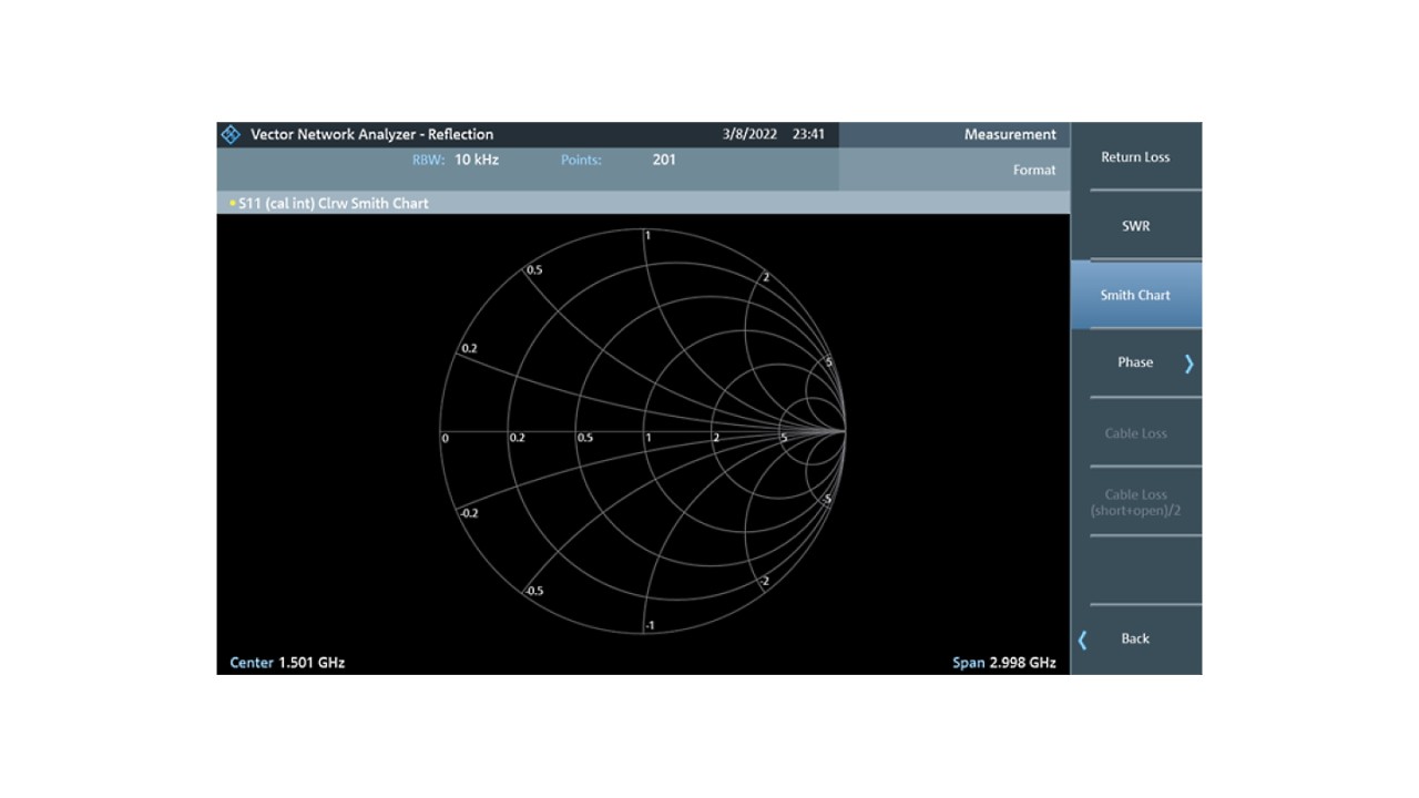
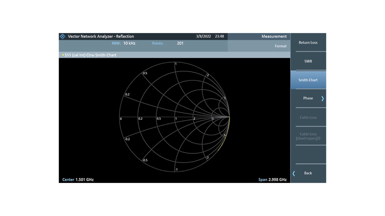
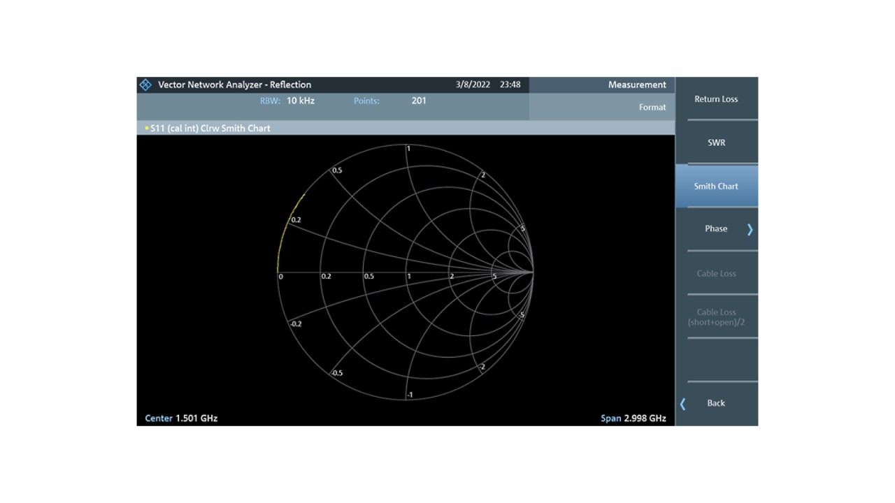
The result described is more or less good if one disregards subtleties that can be improved by correctly assigning the S-parameters of the respective calibration element.
- The calibration kit description file being used as reference in that case was the FSH-Z28. The according parameters do not fit to the elements that have been used for the calibration process. Best way would be to use adequate s-parameter files if they have been provided or are available.
- The calibration always is bound to a reference plane which is at the dedicated point, where the inner conductors of the plug and the socket meet. The reference file describes some parameters like e.g. the delay to open / short /match etc. With this information the calibration process is able to calculate out the delay and the additional impact of the inner conductor line leading to the open / short / match element.
If one of those elements is investigated afterwards, the reference plane is still at the same point, but -for example- the open or short point of the element is a little bit off. This leads to an additional delay and some real and imaginary parts in addition, which you will see in the smith diagram. It will increase with the frequency as the impact is higher with lower wave length.
Proof:
- If no open element is connected, the Smith chart will show an inductive open over frequency (showing these some millimeters going over the reference point).
- If the open element (with inner conductor) is connected, the smith chart will show a capacitive behaviour because of the line being in parallel with the shield of the element.


