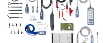
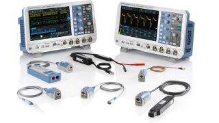
Probes for oscilloscopes

Rohde & Schwarz Probes for oscilloscopes

High quality active and passive probes for oscilloscopes

Rohde & Schwarz offers oscilloscope probes for a variety of applications like debugging of complex electronic circuits, signal integrity measurements of high-speed serial bus signals, as well as characterization of power electronics with high voltage levels. The measurement accuracy and operator safety depend strongly on the probes and accessories that are used.

The Rohde & Schwarz portfolio includes high-quality active and passive oscilloscope probes, power rail probes, multi-channel power probes, high voltage probes, current probes and EMC near-field probes. Besides excellent specifications, they feature reliability and ease of use.

Product List
Product Name
Bandwidth
Max. dynamic range
Bandwidth
100 MHz to 1 GHz
Max. dynamic range
± 3000 V
Bandwidth
38 MHz to 500 MHz
Max. dynamic range
400 V
Bandwidth
8 GHz
Max. dynamic range
20 V
Bandwidth
1 GHz to 6 GHz
Max. dynamic range
± 8 V
Bandwidth
1 GHz to 4.5 GHz
Max. dynamic range
± 5 V, ±60 V (with R&S®RT-ZA15)
Bandwidth
1.5 GHz to 16 GHz
Max. dynamic range
5.0 V
Bandwidth
4 GHz
Max. dynamic range
±0.85 V, (±60 V offset)
Bandwidth
1 MHz
Max. dynamic range
± 15 V / ± 10 A
Bandwidth
25 MHz to 400 MHz
Max. dynamic range
6 kV
Bandwidth
20 kHz to 120 MHz
Max. dynamic range
2.000 A
Bandwidth
30 MHz to 3 GHz
Max. dynamic range
-
Bandwidth
-
Max. dynamic range
-
0 of 3 Compare products
Select at least 2 Products

Probe FAQs

What is an oscilloscope probe?

An oscilloscope probe is a device used to connect a signal source, often a test point in a circuit, to an oscilloscope; a physical connection making the electrical connection. Depending on the signal source and the measurement to make, a probe can be as simple as a wire (e.g. a passive probe) or as sophisticated as an active differential probe, which includes an amplifier to keep the probe input capacitance very low to minimize the influence of the probe on the signal to measure.

Which oscilloscope probe do I need for my measurement?

The first step in selecting the right probe is to analyze the measurement task. Is the circuit to test connected to ground (meaning is a single-ended or a differential probe needed)? What is the maximum possible frequency of the signal (what bandwidth is required)? What is the maximum input voltage that can occur?

Differential or single-ended measurement

Differential probes are required when the circuit to test is not connected to ground, to make voltage measurements on switching power supplies, for example, or for low-noise measurements between differential signals. While there is no physical reason not to use a differential probe on a circuit connected to ground, in these circumstances the performance of a single-ended probe will be superior; a higher input impedance, a lower input capacitance, and a wider dynamic range.

Bandwidth and rise time

Bandwidth is one of the most important parameters when selecting a probe. It defines the effective maximum frequency that can be measured accurately with the probe; at the specified maximum frequency a signal will be displayed more than 3 dB (approx. 30%) weaker than it actually is. For accurate signal representation, the maximum frequency of both the oscilloscope and probe must be significantly greater than the highest frequency to be measured. When measuring digital signals, the measurement bandwidth should be 3 to 5 times greater than the clock rate; for debugging a digital design, a bandwidth 3 times greater is sufficient. For conformance tests on digital interfaces, the bandwidth must be 5 times greater than the clock rate.

When measuring fast rising signals (appearing with steep slopes on the oscilloscope display), such as when characterizing switching power supplies, the critical parameter is the rise time of the oscilloscope and probe. For precise measurements, the rise time should be a factor of 3 to 5 times lower than the rise time of the pulse being measured.

Dynamic range

The dynamic range of a probe defines the maximum measurable input voltage. It is specified for DC voltage and often decreases as the signal frequency increases. For differential probes, a distinction is also made between common mode and differential mode dynamic range. The common mode dynamic range specifies the valid input voltage range for a single differential input, measured with reference to ground. The differential mode dynamic range specifies the maximum measurable input differential voltage.

To accurately measure large-amplitude signals with fast rise/fall times, a sufficiently wide dynamic range must be available at high measurement frequencies. When measuring the residual ripple of DC switching power supplies, very small signals with a large DC component must also be measured. To make the full A/D converter resolution available, modern probes have the option to feed in a DC offset.

In the case of high voltage probes, operator safety is a key consideration. High voltage probes therefore have special insulation and other protective mechanisms to protect against accidental contact. These probes are characterized by the maximum voltage to ground, and also by measurement category. The measurement category defines the measurement environments in which the operator is protected. A probe may only be used in the measurement categories for which it is defined.

Load on the device under test

A measurement system must not excessively load the circuit under test, both to prevent degrading signals and to ensure that the functioning of the DUT is not impaired. The key is to use probes with a high input impedance and a low input capacitance. The resulting input impedance is highly dependent on the frequency and is typically less than 500 Ω at the probe's cutoff frequency.

Passive probes typically have an input impedance of 10 MΩ and an input capacitance of more than 10 pF. Active probes typically have an input capacitance of about 1 pF. It is important to select the right probe accessories for contacting with the DUT. Long pins and leads increase the capacitance and inductance, lower the maximum measurement bandwidth, and lead to excessive overshoot and ringing artifacts at the pulse slopes.

Expanded functions and probe accessories

In addition to the performance parameters, supplemental probe functions for simplifying daily tasks should also be considered. Examples in many Rohde & Schwarz active probes include an integrated digital voltmeter or a micro button. With the voltmeter, check the voltage without needing to change any connections. The micro button can be configured to provide direct control of the oscilloscope from the probe.

The diverse accessories offer flexibility during test point contacting, make the operator's day-to-day work easier and help prevent measurement errors. Available accessories include rigid and spring-loaded tips, browsers, adapters and extension leads. Rohde & Schwarz offers a comprehensive set of accessories for every probe.

What is a power rail probe?

Power rail probes are designed to measure small AC characteristics of DC power rails. Due to their typical attenuation factor of 1:1, power rail probes add very little noise to the measurement. Some power rail probes include a built-in offset of up to ±60 V, to make maximum use of the oscilloscope vertical sensitivity (i.e. more bits of the oscilloscope’s ADC), resulting in a more accurate measurement with lower noise. In addition, the offset eliminates the need to use AC coupling or DC blocking caps, which impede the ability to see true DC values and drift. Power rail probes with bandwidths of up to 2 GHz and a slow rolloff help to capture high-frequency transients and coupled signals; the high input impedance (typically 50 kOhm) minimizes disturbance to measured rail signals

How does a differential probe work?

Differential probes measure the difference in signal level between any two measurement points. In contrast, a single-ended probe measures the difference between a single point and ground potential. Differential probes are especially popular for measuring high-frequency signals or signals of very low amplitude (i.e. approaching the noise floor). Differential probes require an differential amplifier to convert the difference between the two signals into a voltage that can be sent to the (single-ended) oscilloscope input.

Which probe is required for power electronics measurements?

When evaluating power electronics, several measurement scenarios are typical:

  • Small voltages at large common mode voltages
  • Different voltage levels at different potentials at the same time
  • Fast rise-/ fall-times – in particular for wide-bandgap (WBG) materials like GaN, SiC
  • Floating Measurements on multiple signals channels
  • Current measurements

In principle, differential high-voltage probes are ideal for these types of measurement. With up to 200 MHz bandwidth and an excellent common mode rejection ratio (CMRR) over a broad frequency range, the R&S®RT-ZHD high voltage differential probes are ideal for measurements on fast-switching semiconductors. Very low added noise results in high-quality measurements. With 0.5% ensured gain accuracy in the signal path and a DC voltmeter (R&S®ProbeMeter) with 0.1% accuracy integrated into the probe head, the R&S®RT-ZHD probes provide the best available precision in their class. Very low drift makes regular calibration during measurements unnecessary. To measure ripple voltages on the DC link, high offset voltages must be compensated for, to measure with high vertical sensitivity. Due to its integrated offset circuit, the R&S®RT-ZHD probes offer an offset voltage range that is independent of the vertical setting of the oscilloscope and the attenuation factor on the probe. Measure the smallest of ripple voltages on large DC link voltages without compromising sensitivity

Typical measurement parameters to evaluate power electronics are:

  • Power Consumption / Efficiency / Standby Power
  • Power Quality / Power Factor
  • Voltage and Current Waveform Analysis
  • Ripple
  • Inrush Current / Transients
  • Startup / shutdown behavior
  • Load regulation
  • PWM (pulse width modulation) analysis
  • EMC / Harmonics analysis

Request information

Do you have questions or need additional information? Simply fill out this form and we will get right back to you.

Marketing permission

Your request has been sent successfully. We will contact you shortly.
An error is occurred, please try it again later.
General and legal information

Manufacturer's recommended retail price (MSRP). The price shown does not include VAT. Prices and offers are only intended for entrepreneurs and not for private end consumers.

You may use the electronic signature via DocuSign to submit your information to enroll with the Rohde & Schwarz Customer Delegated Administration program. DocuSign processes the information provided according to their . The minimum system requirements for using the DocuSign system may change over time. The current system requirements are found

Terms & Conditions of the Prize Draw 10 years Rohde & Schwarz oscilloscopes

1. The prize draw “10 years Rohde & Schwarz oscilloscopes” (herein referred to as “Draw”) is organized by Rohde & Schwarz GmbH & Co. KG, Mühldorfstraße 15, 81671 Munich, Germany, Tel. +49 89 41 29 0 (herein referred to as “R&S).

2. All participators can register to the draw during January 01, 2020 to December 31, 2020 with their name, company name and business e-mail.

3. Participation is free of charge and not dependent on the purchase of goods or services.

4. The draw is only open to legal entities and only the legal entities are able to win the prizes. An individual person is not allowed to participate on its own name and its own account but as a representative of a legal entity filing the participation form in the name of and on behalf of the legal entity.

5. The prizes to win are 1 of 10 R&S®RTB2000 within the time frame January 1, 2020 to December 31, 2020:

Prize: 1x R&S®RTB2000 Digital Oscilloscope

6. The draw takes place at Rohde & Schwarz headquarters, Muehldorstrasse 15, 81671 Munich. The winner of the prizes will be informed by e-mail within 5 (5) working days.

7. The authorized representative of the legal entity shall inform Rohde & Schwarz about the acceptance of the price. In case of the denial of the acceptance, or no answer within two (2) weeks, a new winner will be drawn. If no winner can be determined within four (4) weeks, the draw ends and the prize forfeit.

8. R&S’ employees and members of their families and also person being familiar with the process of the draw and members of their families are excluded from filling the participation form.

9. No cash equivalent or exchange of prizes is allowed. Prizes are non-transferable. All taxes, levies, duties, fees and other charges levied in the participant´s country shall be borne by the participant.

10. Personal data will be processed only for the purpose of this prize draw and deleted four (4) weeks after the draw, if not agreed otherwise.

11. Any Participant who does not comply with these Terms & Conditions may be disqualified by R&S from this Competition. In such cases, prizes can also be withdrawn retrospectively. In case a prize is withdrawn retrospectively due to the non-compliance with these Terms & Conditions, it shall be returned by the respective participant at his cost to R&S’ address mentioned under Nr.1 and a new winner will be drawn.

12. The participants cannot claim the prizes of this draw and no legal recourse is permitted in this respect.

13. The draw and any contractual relationship arising therefrom between R&S and the respective participant shall be governed by and construed in accordance with the laws of Germany, without any recourse to the conflict of laws. The courts of Munich, Germany, shall have exclusive jurisdiction in case of any disputes arising directly or indirectly from the participation in this Competition.

* “fast delivery” inside 7 working days applies to the Rohde & Schwarz in-house procedures from order processing through to available ex-factory to ship.