Key facts
- Power measurement range: 50 µW to 12 kW
- Frequency bandwidth: DC to 100 kHz
- Sampling rate: 500 ksample/s
- Supports three switchable crest factors
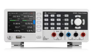
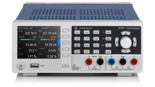
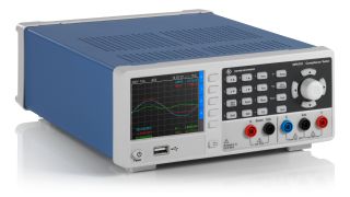
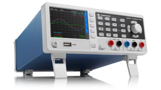
- Latest Rohde & Schwarz design featuring in-device graphical analysis and compliance evaluation


Key facts
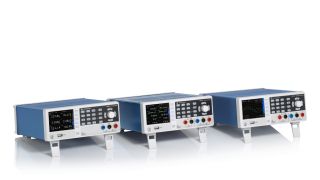
the compact class, that has it all
The R&S®NPA series of single phase power analyzers is a comprehensive range of compact testers meticulously designed for AC/DC load or standby current characterization with fundamental accuracy of 0.05% and low current measurement down to 5 milliamps. Unlike other competitors on the market, these analyzers:
Evaluation functions according to IEC 62301, EN 50564, or EN 61000-3-2
All tests conducted with our compliance testers adhere strictly to the following standards:
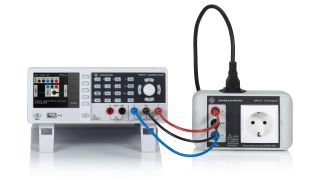
Typical test setup with R&S®NPA-Z1 socket adapter
Graphical view over one waveform period
Utilize a graphical representation to depict occurrences such as fast switch-on operation. This approach simplifies comprehension and helps compare the switching on and the steady-state operations of a device. The system can continuously record 8192 samples with durations of 16 milliseconds to 67 seconds. After a trigger event (similar to a single-shot capture on an oscilloscope), voltage and/or current are graphically plotted.
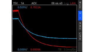
Inrush view showing the switch-on operations
Graphical display versus time
This graphical mode can plot up to two measured variables against time, similar to the roll mode in oscilloscopes. Primarily used observing longer time periods, it can accommodate 40 seconds to 80 minutes of data on the display. Decide on the plotting variables and adjust the timebase, while the vertical trace scaling is done automatically. When operating, the numerical representations of maximum and minimum values are visible on the screen for enhanced analysis
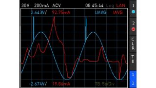
Simultaneous display of voltage and current versus time
Oscillograph waveform chart
This function helps create a graphical representation of voltage, current, and/or power across a single waveform period, similar to the display format on an oscilloscope. The period is automatically determined by the R&S®NPA power analyzer . An automatic hardware trigger initiates each acquisition and the waveform is continuously refreshed. Alongside waveform visualization, the R&S®NPA furnishes numerical outputs for RMS voltage, RMS current and power, with softkeys for selecting displayed or concealed traces
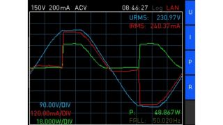
Simultaneous display of voltage, current and power for one period
Harmonics as bar chart or table view
Harmonic mode enables the computing of root mean square (RMS) values and phase angles for harmonics. The accompanying bar chart elegantly visualizes patterns for up to 50 voltage and/or current harmonics, while the tabular presentation has comprehensive insights into magnitude and phase values per harmonic. Users can also selectively display odd or even harmonics. The intuitive interface allows seamless navigation through the data, with cursors or a rotary knob so that users can focus on individual harmonics, highlighted in a distinctive yellow.
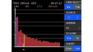
Harmonics visualized as bar chart
Real-time integrator
The integrator function serves a special purpose in unstable power measurements. The function is designed to compute and present the cumulative DUT power or energy consumption across a designated time span in both the active and standby states. Users can flexibly select their preferred acquisition mode, choosing between manual, time-based or event-based options. All R&S®NPA models deliver results in various formats, including positive, negative, and total watt-hours, with continuous updates in real time.
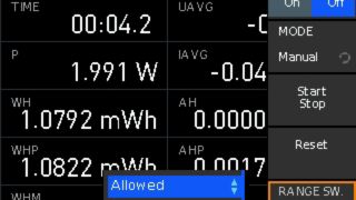
Integrator mode selection
| Electrical specifications | ||
| Analog bandwidth | DC to 100 kHz | |
| Frequency accuracy | 0.1 % of reading | |
| Basic accuracy | 0.05 % of reading | |
| Sampling frequency | 500 kHz | |
| Input impedance | 2 MΩ | |
| Current measurement range | 1 mA to 20 A | |
| Voltage measurement range | 1 mV to 600 V | |
| Power measurement range | Depends on combination of voltage and current ranges | 50 µW to 12 kW |
| Display and interfaces | ||
| Display resolution | 5 digits, 10 updates/s | |
| Remote control interfaces: standard | All models | USB-TMC, USB-CDC (virtual COM), LAN |
| Remote control interfaces: optional | R&S®NPA501-G, R&S®NPA701-G | IEEE-488 (GPIB) |
| Display | 320 × 240 pixel (QVGA-color) | |
| Special functions | ||
| Basic | All models | active power, apparent power, reactive power, lambda power factor, phase shift, frequency, voltage (RMS and average), current (RMS and average), total harmonic distortion, energy, data logging |
| Graphical | R&S®NPA501(-G), R&S®NPA701(-G) | trend chart mode, inrush mode, harmonics mode, waveform mode |
| Advanced | R&S®NPA501(-G), R&S®NPA701(-G) | limit testing, input for external probe and shunt, analog input and output, digital input and output, minimum & maximum voltage, current and power |
| Compliance evaluation | R&S®NPA701(-G) | Standards: IEC62301, EN 50564, EN 61000-3-2 |
| General data | ||
| Rated mains voltage and frequency range | AC | 100 V to 115 V/230 V at 50 Hz to 60 Hz |
| Rated power | 35 W (meas.) | |
| Operating temperature range | +5 °C to +40 °C | |
| Dimensions | 222 mm × 97 mm × 291 mm (8.74 in × 3.82 in × 11.5 in) |
|
| Weight | approx. 3.25 kg (7.16 lb) | |

Order number 3657.8911.02
Mains adapter, EU version

Order number 3657.8911.03
Mains adapter, UK version

Order number 3657.8911.04
Mains adapter, US version

Order number 3657.8911.05
Mains adapter, CHN/AUS version

Order number 3622.4690.02
AC/DC current probe, 30 A, 4 mm connectors

Order number 3622.4684.02
AC/DC current probe, 1000 A, 4 mm connectors

Order number 5800.2054.02
19" rack adapter, 2HU, for R&S®NGE100B/NGC100/NPA and R&S®HMC series
Related products


