USB power delivery compliance testing with Rohde & Schwarz oscilloscopes

One of the key advantages of USB power delivery (USB PD) supported by USB Type-C™ connectors is the capability to transmit power up to 100 W. Using low speed signaling, the devices negotiate a USB PD profile. Suppliers of USB Type-C components and device vendors utilizing the USB PD standard need to ensure interoperability in terms of protocol handshake and signal integrity.

Your task

Confirm appropriate power negotiation between two USB Type-C interfaces with the USB power deliver compliance test. Apart from the PHY layer compliance, protocol compliance for all types of system topologies also needs to be tested.

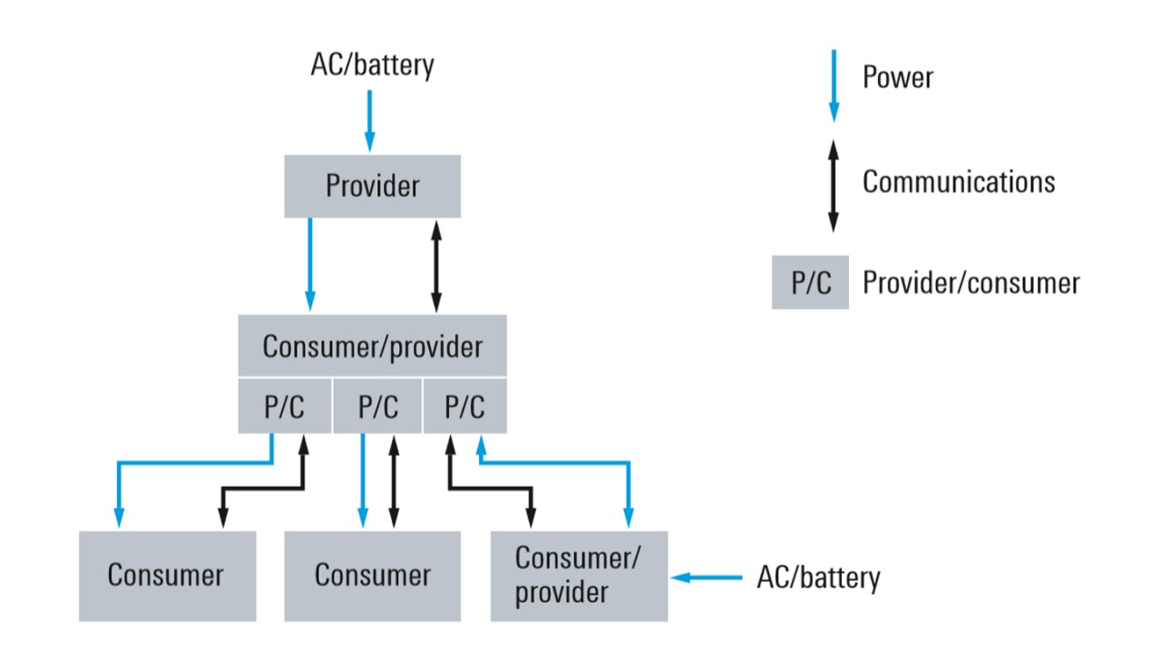
USB power deliver topologies
Open Lightbox

Background

USB power delivery

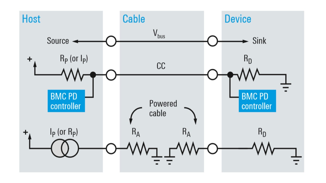
The USB Implementers Forum (USB-IF) enhanced USB 2.0 and USB 3.1 with the USB power delivery specification. This specification enables flexible power delivery up to 100 W (up to 20 V and 5 A). USB power delivery works most effectively with USB-IF defined USB Type-C connectors and cabling that are certified up to USB 3.1 Gen 2 data rates (10 Gbps). The new design supports reverse plug orientation for easy connection. The 24-pin doublesided USB Type-C connector includes high-speed data transmission lanes and an enhanced power delivery interface. USB hosts, devices and accessories negotiate power delivery capabilities via the USB PD communications protocol that is executed on the newly introduced configuration channel (CC). This handshake confirms the providerconsumer relationship and verifies the maximum possible power profile. The diagram below explains the different USB PD topologies supported for power providers, power consumers or dual role devices.

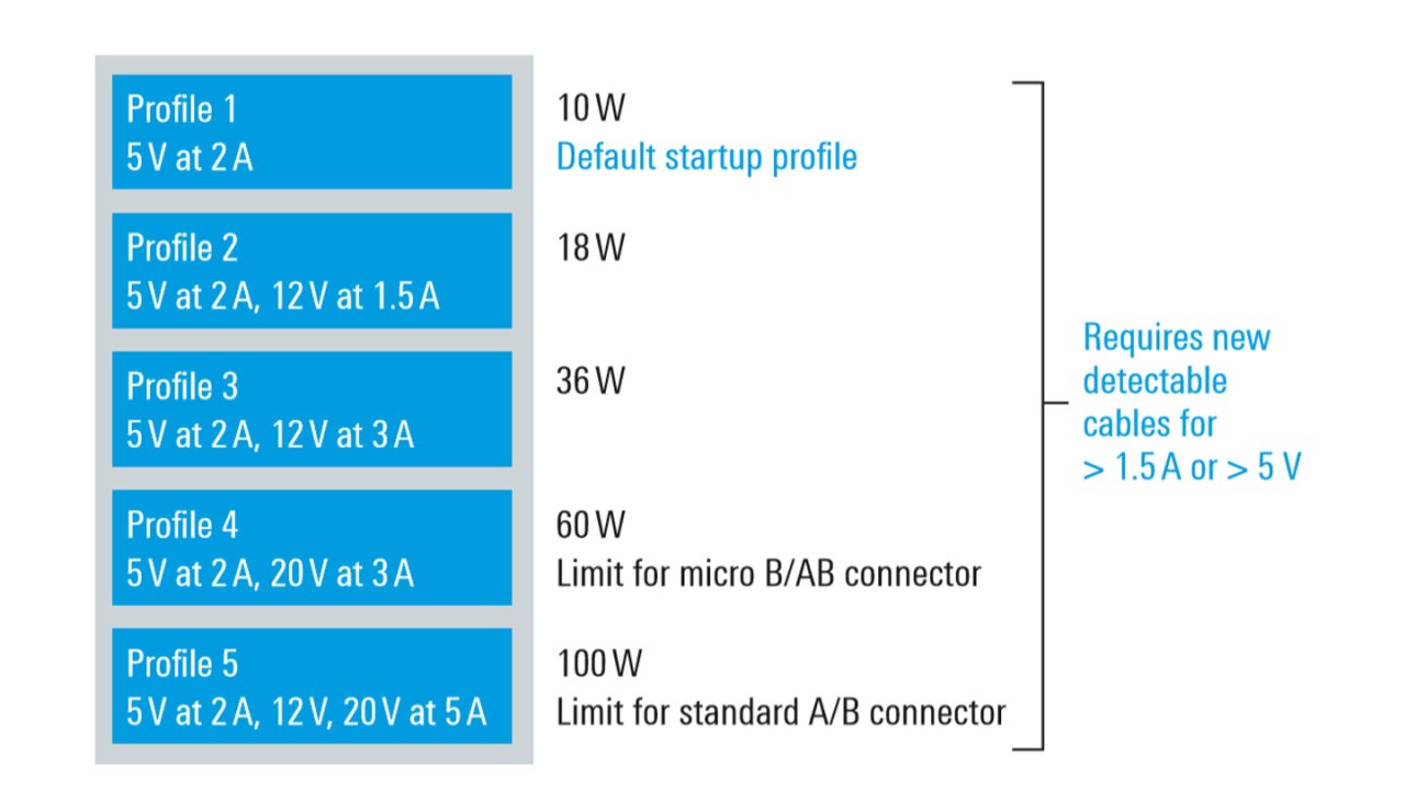
USB power delivery profiles
Open Lightbox

USB Type-C interfaces provide the power via four power supply pin pairs (Vbus). USB-IF has defined five different USB PD profiles for the industry to work with.

Full-featured USB Type-C cables and adapters are electronically marked (e-mark) and contain an ID function chip that is accessible via the CC interface. The test of the e-mark functionality is part of the USB power delivery compliance test specification (CTS).

USB connection with focus on power delivery negotiation
Open Lightbox

BMC PHY integrity

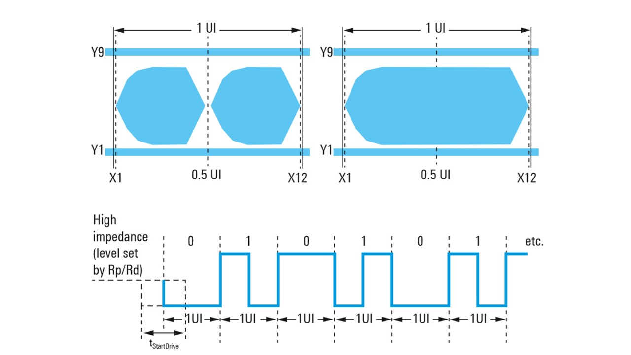
The USB PD protocol on the CC communications interface uses biphase mark code (BMC) encoding to exchange the power profiles between two USB Type-C interfaces.

To ensure interoperability between USB components and devices, and to avoid any damage due to overvoltage and current, it is important that the BMC signal be communicated as specified in the standard. BMC PHY signaling is therefore tested with compliance masks. The modulated signal sequences of logic “one” and “zero” are evaluated separately in the two different mask profiles shown on the next page.

USB PD BMC signal scheme and compliance mask for “one” (left) and “zero” (right)

Rohde& Schwarz solution

USB PD compliance testing confirms an appropriate power negotiation on the CC link of USB Type-C interfaces at frequencies of 270 kbps to 330 kbps and verifies the quality of the supplied power on the Vbus pins. The key selection parameters for an oscilloscope as the main signal acquisition tool for USB PD compliance testing are high measurement dynamic range, fast acquisition and processing, as well as a native 1 MΩ input for the current probes.

Rohde & Schwarz offers, in collaboration with the industry partner Granite River Labs (GRL), a compliance test solution using the R&S®RTE or the R&S®RTO oscilloscope. The GRL-USB-PD analysis software from GRL controls the test equipment and performs the electrical and protocol tests.

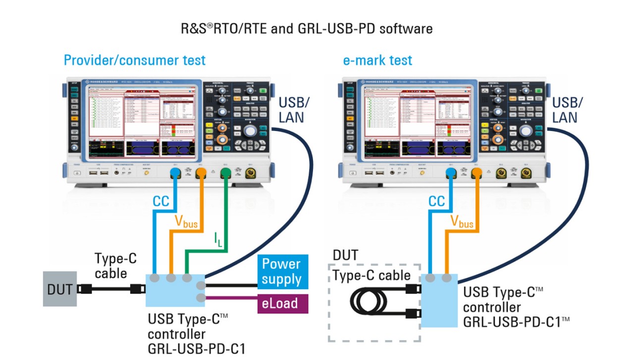
Test setups

The test setup depends on the role of the DUT. In all cases the R&S®RTE or R&S®RTO oscilloscope acquires the USB PD waveforms for compliance analysis and protocol verification. For measuring the voltage (Vbus) and the current (IL) on the Vbus supply, a passive voltage probe and a current probe are required. Another voltage probe connects to the CC communications link. The test of USB Type-C cables and adapters focuses on the validation of the e-mark code on the CC signal link.

Test setups
Test setups

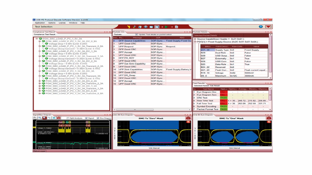
GRL-USB-PD compliance test tool

GRL developed GRL-USB-PD, the USB PD compliance test software, based on the USB Type-C CTS. The tool uses the acquired waveforms to generate eye diagrams for compliance mask testing and performs measurements for electrical parametric testing. It also decodes the BMC signaling for protocol testing. For USB Type-C cables and adapters, the GRL-USB-PD tool supports USB Type-C e-mark compliance tests. In combination with the GRL USB Type-C test controller, the GRL-USB-PD software provides a complete automated compliance test solution. At the end of the tests, the software generates a comprehensive test report.

GRL-USB-PD testing USB PD BMC eye diagram (source: GRL).
Open Lightbox

The GRL-USB-PD software covers the following tests:

  • Electrical physical layer compliance (BMC-PHY)
    • Eye diagram
    • Timing measurements (e.g. bit rate, rise time)
    • CRC check
  • USB PD protocol compliance and decode (BMC-PROT)
    • CC line packet decode
    • VDM decode for USB Type-C cables and adapters
  • Power source/sink tests (BMC-POW)

USB Type-C test controller

GRL developed USB Type-C test controller hardware (GRL-USB-PD-C1). It has built-in USB PD controller functionality, a power supply for testing consumers and provides connectivity to the DUT and the remaining test equipment. The controller configures the DUT to send out appropriate USB PD responses for compliance testing.

E-load

A different load has to be applied for each tested power profile to ensure that the USB PD provider supplies sufficient power. Electronic loads from Chroma Systems Solutions, for example, are able to simulate different power scenarios.

Additional USB test capabilities with the R&S®RTE and R&S®RTO oscilloscopes

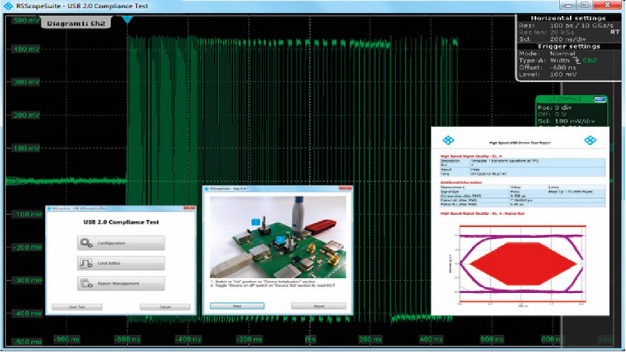
R&S®RTO-K21 USB compliance test software.
Open Lightbox

USB 2.0 compliance testing

Equipped with the R&S®RTO-K21 USB 2.0 compliance test option, and together with the R&S®RT-ZF1 USB compliance test fixture, the R&S®RTO can be used for compliance testing of USB 2.0/1.1/1.0 and HSIC interfaces. Based on the R&S®ScopeSuite, compliance testing is fully automated and offers full flexibility for debugging, testing and compliance certification.

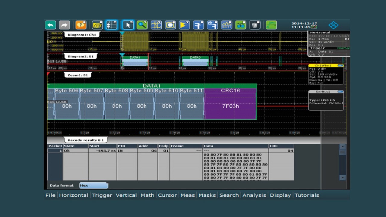
R&S®RTE/RTO-K60 USB triggering and decoding.
Open Lightbox

USB 2.0 triggering and decoding

The R&S®RTE-K60/RTO-K60 option for the R&S®RTE/RTO supports protocol decoding and triggering for USB 2.0/1.1/1.0 and HSIC. Fast processing, flexible display of the decoding data as well as the comprehensive set of trigger events make this option an essential tool for debugging embedded designs that have USB interfaces.