Your task
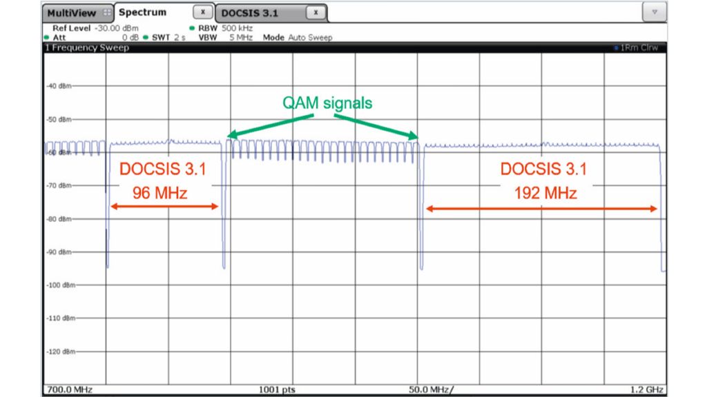
The need for higher data rates and flexibility for IP and cable TV (CATV) has led to the introduction of DOCSIS 3.1. With channel bandwidths up to 192 MHz in the downstream and 96 MHz in the upstream and the cable network frequency extension up to 1.2 GHz (1.8 GHz as a future extension), cable components must meet significantly higher technical requirements. Testing requirements include supporting a full channel load and coexistence of both DOCSIS 3.0 and DOCSIS 3.1 signals (in some cases analog TV as well).
Rohde & Schwarz solution
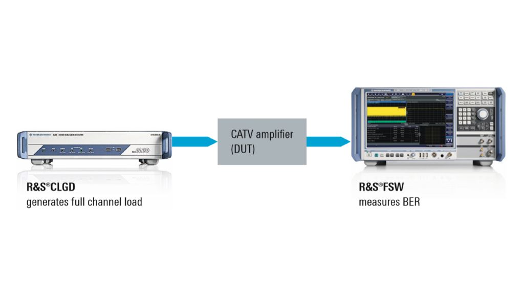
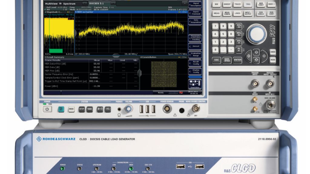
The R&S®CLGD is the only flexible and compact solution available on the market that can meet these testing requirements. The introduction of much wider bandwidths for DOCSIS 3.1 along with higher constellation modes (up to 16kQAM) require very powerful spectrum and signal analyzers. The R&S®FSW is ideal since it can measure MER that is typically 57 dB and higher and also provide BER measurements based on DOCSIS 3.1 signals.
Bit error rate (BER) test solution for DOCSIS 3.1
The bit error rate (BER) is an important measurement for CATV component manufacturers. In order to measure the BER, the data sequence sent by the signal generator must be known by the signal analyzer in advance.
For the R&S®FSW, this is not necessary because it uses the detected bit errors from the LDPC decoder in the R&S®FSW-K192 DOCSIS 3.1 analysis option to calculate BER. The R&S®FSW compares the measured (demodulated) data with the available reference information and calculates the BER by itself.
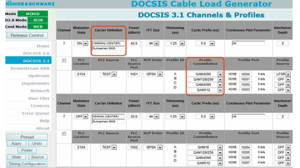
The R&S®CLGD can generate a full channel load with DOCSIS 3.1 signals. A typical signal configuration for DOCSIS 3.1 is shown in the figure on the left. The most important parameters are highlighted in the red boxes (frequency and constellation of the DOCSIS profiles).
In a similar way, the R&S®CLGD can generate a full channel load with DOCSIS 3.0 signals to occupy the entire CATV frequency spectrum.
The RF output frequency and power of the signals can be independently adjusted, making R&S®CLGD a very flexible cable load generator for simulating complex scenarios to the DUT.
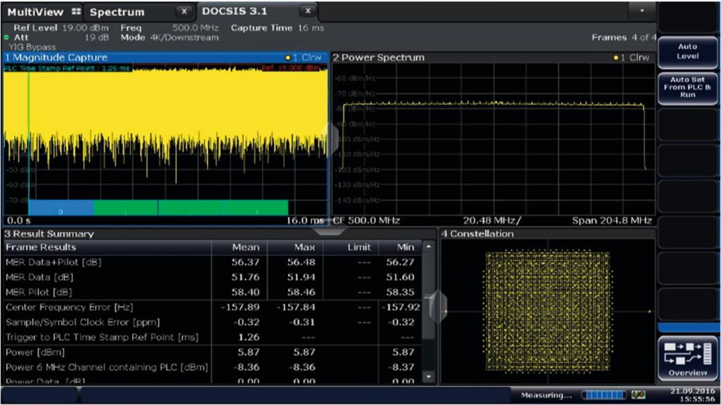
The RF output from the DUT is directly connected to the R&S®FSW RF input port. On the R&S®FSW, select “Mode” and choose “DOCSIS 3.1” from the popup menu. Then choose the downstream measurement option and set the correct frequency. On the right-hand menu, press “Auto Level” and “Auto Set From PLC & Run” to automatically adjust all DOCSIS 3.1 parameters.
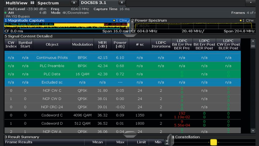
In the R&S®FSW view mode, select the “Signal Content Detailed” option to display a detailed analysis of all the PLC data, codewords on different DOCSIS 3.1 profiles, etc. BER measurements are provided for pre-LDCP and post-LDPC. This example shows a DOCSIS 3.1 profile with 4096QAM. This test can be performed either by increasing the RF output power or by adjusting the AWGN settings on the R&S®CLGD. The user can monitor these changes by observing the BER analysis window.
Conclusion
The R&S®CLGD and R&S®FSW offer all the necessary functionality for testing amplifiers, DFB lasers and other components in a DOCSIS 3.1 network. Plus the two instruments can be used to generate and analyze existing DOCSIS 3.0 signals, making the solution very cost efficient.


