Military bus protocol testing

Military bus protocol testing

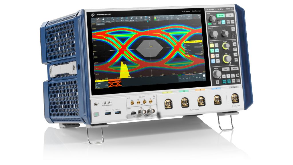
Multipurpose digital oscilloscopes for bus testing and communications protocol debugging

Expand the analysis capabilities of your oscilloscope with different application options. These include protocol-based triggering and decoding, automated compliance tests for the most popular interface standards, general analysis such as jitter or power as well as vector signal analysis.

As the aerospace and defense industry uses a wide variety of buses, the multi-purpose, app-customizable oscilloscopes by Rohde & Schwarz are a highly valuable asset in any defense lab for testing wired digital bus protocols commonly used in defense industry applications, such military radios integrated in combat aircrafts, helicopters or tanks. The military communications market aims to analyze these buses in order to prove a certain criticality level, robustness and reliability of the system.

However, the reliability cannot be on the same level when dealing with widely different priorities. For example, the reliability of the bus data exchange between the navigation system and a flight control system of an aircraft cannot be compared to the requirements of data exchange between a military land vehicle driver's dashboard and the windshield wiper system. This calls for flexible test and measurement solutions to meet specific MILBUS testing demands.

For military applications, our oscilloscopes are ideal for tasks such as triggering and decoding as well as compliance test of the most commonly used buses to exchange data inside the line-replaceable units (LRU). Among them are Serial / RS232, DDR3 / 4 PCIe, eMMC or even USB. The oscilloscopes are an indispensable tool also for tasks at a higher level. This includes commonly used buses to exchange information between LRUs such as ARINC 429, MILBUS1553, SpaceWire, CAN / LIN or Ethernet / AFDX.

The test and measurement solutions by Rohde & Schwarz enable flawless performance and reliability on every level, from testing of assemblies and components up to verification of the complete radio communication system.

Let us know how we can support you.

White paper: Avionics – Digital design and bus interface testing

White paper: Avionics – Digital design and bus interface testing

Download this publication to get a deeper understanding of digital electronics communications test solutions for ensuring the signal, data and power integrity needed during digital design, integration and performance verification. Both legacy and next generation military electronic computers need wired communication integrated systems, subsystems and their integral component parts.

FAQs

What instrument is a best fit for protocol debugging?

The oscilloscopes are. An oscilloscope measures the change in voltage level of electrical as time passes. An oscilloscope has a screen used as a graphical display, with voltage level shown on the vertical axis (Y) and time on the horizontal axis (X). The curve on the screen (representing the signal waveform), shows the changes in the voltage level, with time.

The trigger setting of an oscilloscope determines the time at which the oscilloscope starts to acquire the signal. The basic concept behind the oscilloscope trigger function is that some of the incoming signal is fed into a comparator circuit. When the voltage of the waveform reaches a previously defined trigger condition (e.g. it crosses a threshold level), the data acquisition is initiated. This is the main concept used to debug and decode bus signals, as single or multiple bits can be decoded during each trigger.

Do Oscilloscopes have specific applications for MILCOM?

Modern digital oscilloscopes support a multitude of specific measurements and applications for troubleshooting circuits or checking the quality of acquired signals. Applications provided by Oscilloscopes can be generic or industry/segment specific.

Examples of MILCOM specific applications are the MILBUS or Arinc-429 bus trigger and decode for debug and, examples of generic applications are the compliance tests (such as USB or Ethernet), jitter measurements, frequency response analysis using Bode plot functions, power electronics measurements, digital signal analysis for mixed signal designs, EMI analysis, automotive radar debugging.

Which oscilloscope bandwidth do I need to decode MILBUS signals?

The general statements are:

  • For non-sinusoidal waveforms like e.g. rectangular clock-signals, the oscilloscope bandwidth should be at least 3 times the clock signal fundamental frequency for decoding or debugging and 5 times the clock signal for compliance testing.
  • For non-periodic signals the “rise time” t_r, i.e. the fastest / steepest edge of the signal, has to be considered. In this case, the required minimum oscilloscope bandwidth f_BW can be approximated using f_BW = 0.5 / t_r.

Considering a 160ns average rise time for the 1553B MILBUS, then the recommended oscilloscope should have a bandwidth of 3.5MHz. Rohde & Schwarz oscilloscope offer starts at 50MHz, so any oscilloscope could fit these bandwidth requirements.

Sign up for our newsletter

Sign up for our newsletter

Stay up to date on upcoming trends and latest applications.