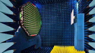
R&S®PWC200 Plane wave converter

For 5G massive MIMO base station testing

R&S®PWC200 Plane wave converter
Open Lightbox
R&S®PWC200 plane wave converter, application image

Key facts

  • Phased antenna array to form plane waves within a ø > 1.05 m quiet zone
  • No near-field to far-field transformation required
  • Four times smaller than CATR based systems
  • Built-in self-test features
  • For R&D and production testing

Measurements of far-field characteristics at very close distances

The R&S®PWC200 plane wave converter is uniquely designed for 5G massive MIMO base station testing solutions in R&D, quality assurance and production as well as over the air (OTA) conformance testing. It has a bidirectional array of 156 wideband Vivaldi antennas in the radiating near field (NF) of the device under test (DUT). The phased antenna array can form planar waves inside a specified quiet zone surrounding a 5G massive MIMO base station DUT for real-time radiated power and transceiver measurements (EVM, ACLR, SEM, etc.).

Features & benefits

Compact base station test system design

Far-field measurements in near-field range

The R&S®PWC200 can drastically reduce measurement distances needed for far field characterization. OTA testing of 5G massive MIMO base stations with apertures of 1 m at a frequency of 3.5 GHz is possible from a distance of just 1.5 m. By comparison, direct far field measurements require 23.5 m. The R&S®PWC200 uses less floor space in test labs and production facilities without compromising measurement accuracy.

R&S®PWC200 with reference antenna
Open Lightbox

R&S®PWC200 with reference antenna

Versatile quiet zone simulation

Easily configurable quiet zone diameter and test distance

The R&S®PWC200 can synthesize electromagnetic fields programmed when preparing the test setup. R&S®PWC-K10 field simulation software provides simulations that apply various parameters, such as the desired quiet zone diameter and test distance. This flexibility enables the R&S®PWC200 to measure base stations of different sizes with the same static test setup.

Field simulation results
Open Lightbox

Field simulation results

Sample results for electric field distribution at 3.5 GHz in the quiet zone at a distance of 1.5 m from the antenna array

Automated field calibration

Fast and automated self-calibration in the field with R&S®PWC software

R&S®PWC-K50 field and path loss calibration software works with the R&S®TC-TA18 calibration antenna to automatically calibrate and verify the R&S®PWC200 in the field. This process does not require the opposite antennas to be moved. The periodic maintenance and verification of high measurement accuracy is simple and quick.

R&S®PWC200 with calibration antenna installed
Open Lightbox

R&S®PWC200 with calibration antenna installed

Calibration and verification system setup with the R&S®PWC200 on the left and a calibration antenna on the right.

Electronic near-field scanning

Automated power factor calibration and power density measurement

R&S®PWC-K80 power density measurement software measures the planar distribution of power density radiating from a 5G massive MIMO base station. This feature is especially useful in production testing without positioning systems. The R&S®PWC200 can easily verify electronically steered beams with small tilt angles of +/- 10° for base stations and display peak areas.

Power factors spatial distribution graphics
Open Lightbox

Power factors spatial distribution graphics

Examples of RMS (left) and peak (right) power densities. Spatial distribution for a TDD signal at 3.4 GHz.

R&S®PWC200 software tools

Comprehensive R&S®PWC 200 software tools allow easy configuration

The R&S®PWC200 can be controlled by either the R&S®AMS32 system software or customer-specific OTA software. Four software tools are available as standalone executable programs: field simulation (R&S®PWC-K10), field and path loss calibration (R&S®PWC-K50), self-test and hardware verification (R&S®PWC-K70) and power density measurements (R&S®PWC-K80). The user interface is clearly arranged and the configuration data sets are visible in CSV file format.

R&S®PWC200 system software architecture
Open Lightbox

R&S®PWC200 system software architecture

Related solutions

5G NR testing

More information

5G OTA/massive MIMO testing

More information

IoT testing

More information

Request information

Do you have questions or need additional information? Simply fill out this form and we will get right back to you.

Marketing permission

Your request has been sent successfully. We will contact you shortly.
An error is occurred, please try it again later.