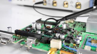
Device setup
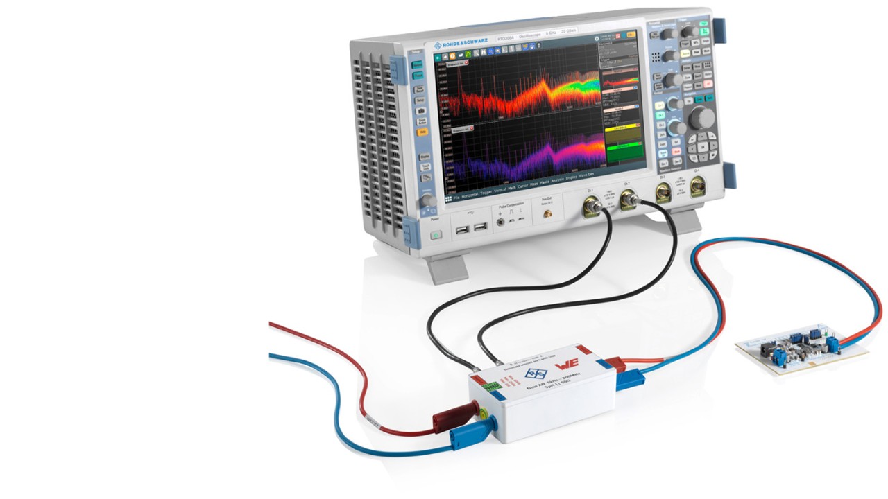
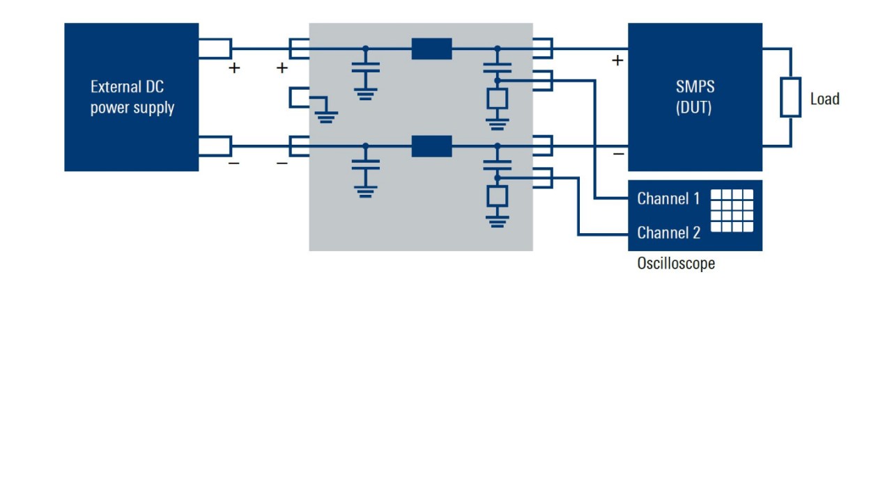
The LISN must be connected between the device under test and the external power supply to measure a power supply’s conducted emissions. The LISN coaxial output must be connected to the oscilloscope with a coaxial cable with 50 Ω input impedance and activated at the oscilloscope to ensure proper matching. The following steps must be carried out on the oscilloscope to measure the spectrum:
- Activate the FFT function and configure the maximum and minimum frequencies as well as the resolution bandwidth
- Adjust the vertical sensitivity in the time domain window to prevent overdrive in the input channel when the device under test is powered
- Switch off the power supplying the DUT for a reference measurement. This reveals the noise floor of the setup which is not coming from the DUT
- Switch on the power again and take a measurement. Verify against known conducted emission limits for the DUT on both power conductors. Account for any added LISN attenuation
Case study – homemade DC-LISN performance
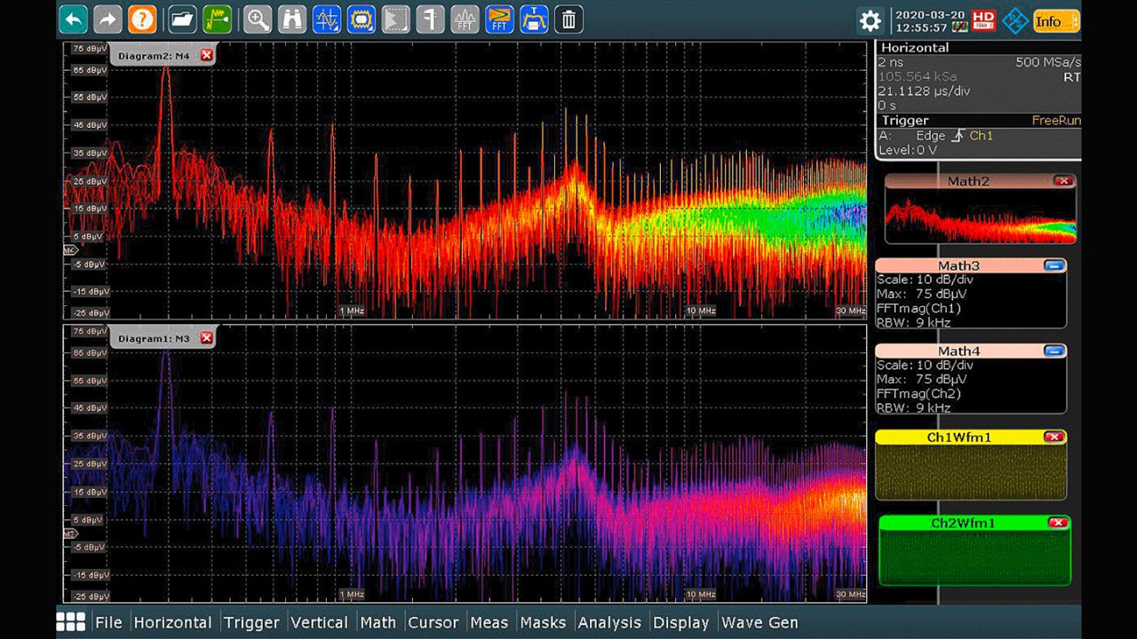
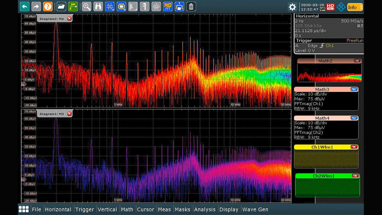
The two screenshots below show a conducted emission measurement using the R&S®RTO2064 oscilloscope with a standard-compliant, off-the-shelf LISN and the homemade LISN designed by Würth Elektronik eiSos GmbH & Co. KG.
Channel 1 and channel 2 display the measured time domain signals on the LISN’s positive and the negative terminals. The LISN attenuates these signals by a factor of 10 dB, which has to be taken into account when comparing with emission limits. The math channels M3 and M4 show the spectrum in dBμV on the DUT input terminal. The noise spectrum generated at the input of the DC-DC converter is clearly visible.
Conducted emission measurements with the Würth LISN show that the max hold spectrum on the input line is very close across the entire frequency spectrum compared to the results from the off-the-shelf LISN.


