Measuring closed loop stability with bode plots
To better describe the application of Bode Plots, closed loop stability of a DC/DC power supply is measured by determining the closed loop response. This can be tested using the voltage injection method. This method adds a very small resistor – usually on the order of 10 ohms – into the feedback loop. A point should be chosen such that the impedance looking in the direction of the feedback loop is much larger than the impedance looking back. A small disturbance signal is then injected across the resistor. This is normally done using a so-called injection transformer to avoid influencing the loop. The response is then measured and Bode plots are generated.
Instruments for measuring closed loop response
Two different categories of instruments can be used when measuring closed loop response. The first of these is a vector network analyzer or VNA. A VNA usually has a very high dynamic range, which allows it to make very precise impedance measurements. One drawback to using a VNA, other than cost and complexity, is that VNA’s are best suited for the characterization of 50 ohm components. Oscilloscopes, on the other hand, are already commonly used in the development of power supplies and allow direct characterization of noise and output ripple. Scopes can now also make stability measurements such as gain and phase margin, power supply rejection ratio, and step response.
Test configuration: How to measure control loop response with an oscilloscope
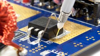
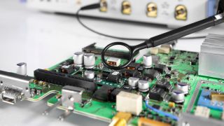
To measure the loop response of the DC-DC power supply, a disturbance signal must be injected into the loop. Thus, a point should be chosen where the impedance looking in the direction of the loop is much larger than the impedance looking backwards. A small resistor is placed at the injection point and the disturbance voltage is applied in parallel to the injection resistor using a wideband injection transformer. The disturbance signal is created by the internal generator of the oscilloscope. Two channels of the oscilloscope are connected to either side of the injection point. Based on the measured values, the oscilloscope generates and displays the Bode plots.
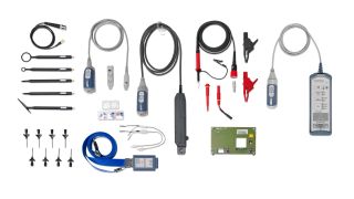
When measuring closed loop response, it’s important to use the right probes. The peak to peak amplitudes at the measuring points can be very low at some test frequencies. For this reason, 1x passive probes are recommended over the more common 10x probes. If the signal is increased to noise ratio, this also improves the dynamic range of the frequency response measurements. It is also important to use a ground spring or a very short ground lead in order to reduce switching noise pickup and inductive ground loops.


