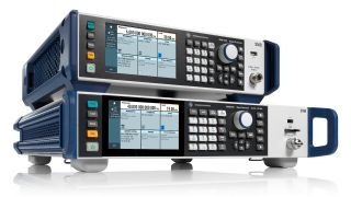
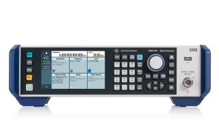
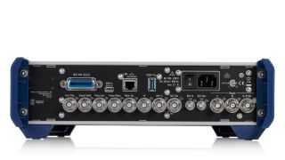
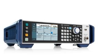
R&S®SMB100B RF and microwave signal generator

R&S®SMB100B RF and microwave signal generator
Open Lightbox
R&S®SMB100B RF and microwave signal generator
Open Lightbox
R&S®SMB100B RF and microwave signal generator
Open Lightbox
R&S®SMB100B RF and microwave signal generator
Open Lightbox
R&S®SMB100B RF and microwave signal generator
Open Lightbox
R&S®SMB100B RF and microwave signal generator
Open Lightbox
R&S®SMB100B RF and microwave signal generator
Open Lightbox
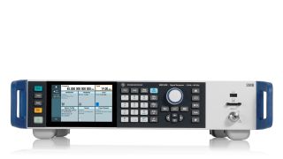
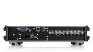
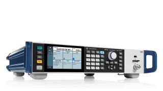
R&S®SMB100B RF and microwave signal generator, hero view R&S®SMB100B RF signal generator, front low R&S®SMB100B RF signal generator, back low R&S®SMB100B RF signal generator, hero view R&S®SMB100B RF and microwave signal generator, front low R&S®SMB100B RF and microwave signal generator, back low R&S®SMB100B RF and microwave signal generator, hero view

Key Facts

  • Frequency range from 8 kHz to 1, 3, 6, 12.75, 20, 31.8 and 40 GHz
  • Outstanding single sideband (SSB) phase noise of < –112 dBc (meas.) at 10 GHz and an offset of 20 kHz
  • Very low wideband noise depending on the frequency range, sometimes well below < –145 dBc (meas.)
  • Highest output power of 34 dBm at 1 GHz, 25 dBm at 20 GHz and 19 dBm at 40 GHz (all is measured)
  • Compact form factor of 2 HU and 3/4 19" width for the R&S®SMB100B RF signal generator (1/3/6 GHz) and 19" width for the R&S®SMB100B microwave signal generator (12.75/20/31.8/40 GHz)

Perfect combination of performance and usability in a compact size

The R&S®SMB100B analog signal generator combines performance and versatility in a small footprint. Outstanding spectral purity and very high output power combined with comprehensive functions and very simple operation characterize the R&S®SMB100B. The R&S®SMB100B analog RF signal generator (3/4 19" width) has a frequency range from 8 kHz to 1, 3 and 6 GHz. The R&S®SMB100B analog microwave signal generator (19" width) has a frequency range from 8 kHz to 12.75, 20, 31.8 and 40 GHz.

Caractéristiques & avantages

Performance and usability in a compact size:

The R&S®SMB100B has outstanding spectral purity, very high output power and comprehensive functions

The R&S®SMB100B RF and microwave signal generator combines performance and versatility in a small footprint, while offering comprehensive functions and user-friendly operation.

  • Frequency range from 8 kHz to 1, 3, 6, 12.75, 20, 31.8 and 40 GHz
  • Compact form factor of 2 HU and 3/4 19" width for the R&S®SMB100B analog RF signal generator (1/3/6 GHz) and 19" width for the R&S®SMB100B analog microwave signal generator (12.75/20/31.8/40 GHz)
  • Context-sensitive online help provides comprehensive information
  • SCPI macro recorder with a code generator that automatically records manual settings and creates executable MATLAB® scripts

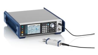
The R&S®SMB100B RF signal generator with connected R&S®NRP power sensor (via USB).
Open Lightbox

The R&S®SMB100B RF signal generator with connected R&S®NRP power sensor (via USB).

Perfect for signal quality

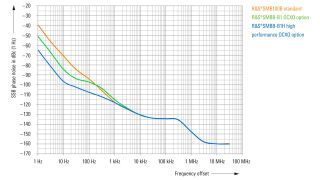
Very low SSB phase noise of < –112 dBc (meas.) at 10 GHz and an offset of 20 kHz

To improve DUTs, signal source quality must be much better than DUT performance. The innovative R&S®SMB100B synthesizer design has very low SSB phase and wideband noise and excellent nonharmonic signal component suppression.

SSB phase noise (1 GHz, 1 Hz BW, meas.)
Open Lightbox

SSB phase noise (1 GHz, 1 Hz BW, meas.)

SSB phase noise for the R&S®SMB100B base unit, with the R&S®SMBB-B1 option (OCXO) and the R&S®SMBB-B1H option (high performance OCXO).

Perfect for output power

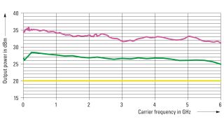
Highest output power of 34 dBm at 1 GHz, 25 dBm at 20 GHz and 19 dBm at 40 GHz (all is measured)

The R&S®SMBB-K31 high output power option for the R&S®SMB100B RF signal generator as well as the R&S®SMBB-K33 high output power option for the R&S®SMB100B (12.75/20 GHz) and the R&S®SMBB-K35 high output power option for the R&S®SMB100B (31.8/40 GHz) are key codes and can be easily activated later on. The R&S®SMB100B RF signal generator lets the high power option be supplemented with the R&S®SMBB-B32 ultra high output power option;
Maximum output power
Open Lightbox

Maximum output power

Measured output power for the base unit, with the high power option (R&S®SMBB-K31) and additional ultra-high-power option (R&S®SMBB-B32).;

Perfect for use

The R&S®SMB100B is very user friendly

  • The RF signal generator is easy to operate, can work with a connected R&S®NRP power sensor and emulate legacy instruments. You can also create your own user menu
  • Context-sensitive online help provides comprehensive information
  • SCPI macro recorder with a code generator that automatically records manual settings and creates executable MATLAB® scripts

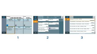
The R&S®SMB100B main screen and user menu
Open Lightbox

The R&S®SMB100B main screen and user menu

Sample user menu. Individual parameters can be set directly in this menu.

Variable reference frequency inputs/outputs

The R&S®SMB100B can output (or input) various reference signals. The 1 MHz to 100 MHz variable external reference frequency input (R&S®SMBB-K704 option) allows the R&S®SMB100B to be easily integrated into existing test environments. The received reference frequency can also be sent to a separate reference output (for details see data sheet). Superb phase stability between multiple R&S®SMB100B instruments is possible with the 1 GHz reference frequency input and output option (R&S®SMBB-B3 option).

Variable reference frequency inputs/outputs (rear view of the R&S®SMB100B RF signal generator)
Open Lightbox

Variable reference frequency inputs/outputs (rear view of the R&S®SMB100B RF signal generator)

R&S®LegacyPro;

Refresh your T&M equipment

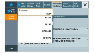
When individual pieces of equipment become obsolete before the entire ATE system, the regular calibration and repair of obsolete equipment is expensive, time consuming and challenging. Replacing obsolete test equipment with equivalent state-of-the-art instruments should be straightforward and require minimal hardware and software changes. R&S®LegacyPro code emulation makes these changes while reducing the workload and eliminating risks.

R&S®LegacyPro code emulation
Open Lightbox

R&S®LegacyPro code emulation

Emulation of legacy generators from Rohde & Schwarz and other vendors.

R&S®NRP power sensor connectivity

An R&S®NRP power sensor can be connected to the R&S®SMB100B

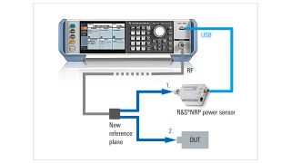
A DUT is rarely connected directly to the generator. There are often cables and other components between the generator and the DUT. This shifts the reference plane from the generator RF output to the DUT. An R&S®NRP power sensor can be connected to the R&S®SMB100B for extremely precise calibration (tenth of a dB) at this new reference plane.

Extremely precise calibration
Open Lightbox

Extremely precise calibration

R&S®SMB100B with external devices: R&S®NRP power sensor (via USB); setup for the target power at the new reference plane.

UCOR (user correction)

Compensation of an external frequency response by the R&S®SMB100B with a connected R&S®NRP power sensor

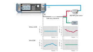
DUTs are often connected to the signal generator via long cables or other frequency-dependent components. Compensating for the frequency response is very important. The R&S®SMB100B has a user correction (UCOR) function. Together with the R&S®NRP power sensor the UCOR values can be automatically determined at the push of a button. A frequency response compensated RF signal is available at the new reference plane for UCOR.

Setup and UCOR function
Open Lightbox

Setup and UCOR function

Relative output power display for cables and other components (with their own frequency responses) between the R&S®SMB100B and a DUT.

Closed loop power control (CLPC)

Dynamic compensation of external frequency responses and drifts by the R&S®SMB100B with a connected R&S®NRP power sensor

The dynamic closed loop power control is a standard feature of the R&S®SMB100B. In combination with an R&S®NRP power sensor it ensures highly accurate and stable input power over time to the DUT regardless of unexpected signal chain losses or gains, unwanted power drifts in the setup or target level changes. The 1GP141 application note describes in great detail the closed loop power control function, the signals that can be used, the suitable signal generators and R&S®NRP power sensors and what needs to be taken into account. Please read the application note before using the closed loop power control for the first time to avoid a possible damage to the DUT.

Available options

Options de fréquence
Produit
Désignation
R&S®SMBB-B101

Numéro de commande 1422.5005.02

Désignation

Frequency option

8 kHz to 1 GHz

R&S®SMBB-B103

Numéro de commande 1422.5105.02

Désignation

Frequency option

8 kHz to 3 GHz

R&S®SMBB-B106

Numéro de commande 1422.5205.02

Désignation

Frequency option

8 kHz to 6 GHz

R&S®SMBB-B112

Numéro de commande 1422.9030.02

Désignation

Frequency option

8 kHz to 12.75 GHz

R&S®SMBB-B120

Numéro de commande 1422.9100.02

Désignation

Frequency option

8 kHz to 20 GHz

R&S®SMBB-B131

Numéro de commande 1422.9175.02

Désignation

Frequency option

8 kHz to 31.8 GHz

R&S®SMBB-B140

Numéro de commande 1422.9246.02

Désignation

Frequency option

8 kHz to 40 GHz

R&S®SMBB-B140N

Numéro de commande 1422.9300.02

Désignation

Frequency option

8 kHz to 40 GHz, limited minimum pulse width

Options oscillateur de référence
Produit
Désignation
R&S®SMBB-B1

Numéro de commande 1422.5305.02

Désignation

OCXO Reference Oscillator

Only one of the R&S®SMBB-B1 or R&S®SMBB-B1H options can be installed.

R&S®SMBB-B1H

Numéro de commande 1422.5405.02

Désignation

High Performance OCXO Reference Oscillator

Only one of the R&S®SMBB-B1 or R&S®SMBB-B1H options can be installed.

R&S®SMBB-B3

Numéro de commande 1422.5505.02

Désignation

100 MHz, 1 GHz Ultra Low Noise Reference Input and Output

R&S®SMBB-K704

Numéro de commande 1422.6301.02

Désignation

Variable Reference Input from 1 MHz to 100 MHz

Options de puissance de sortie
Produit
Désignation
R&S®SMBB-K31

Numéro de commande 1422.5705.02

Désignation

High Output Power, 1/3/6 GHz

R&S®SMBB-B32

Numéro de commande 1422.5740.02

Désignation

Ultra High Output Power 1/3/6 GHz

Requires the R&S®SMBB-K31 option.

R&S®SMBB-K33

Numéro de commande 1422.9946.02

Désignation

High Output Power, 12.75/20 GHz

R&S®SMBB-K35

Numéro de commande 1422.9952.02

Désignation

High Output Power, 31.8/40 GHz

Options de modulation analogique
Produit
Désignation
R&S®SMBB-K22

Numéro de commande 1422.5905.02

Désignation

High Performance Pulse Modulator

R&S®SMBB-K23

Numéro de commande 1422.6001.02

Désignation

Pulse Generator

R&S®SMBB-K24

Numéro de commande 1422.6053.02

Désignation

Multifunction Generator

R&S®SMBB-K27

Numéro de commande 1422.6101.02

Désignation

Pulse train

Requires the R&S®SMBB-K23 option

R&S®SMBB-K720

Numéro de commande 1422.6201.02

Désignation

AM/FM/φM

R&S®SMBB-B5

Numéro de commande 1422.5605.02

Désignation

Stereo/RDS coder, 1/3/6 GHz

Requires the R&S®SMBB-K720 option

Extras
Produit
Désignation
R&S®SMBB-B86

Numéro de commande 1422.5805.02

Désignation

Remote control interface (GPIB and USB)

For instruments with frequency option R&S®SMBB-B101, -B103 or -B106

R&S®SMBB-K986

Numéro de commande 1422.9969.02

Désignation

Remote Control Interface (GPIB and USB)

For instruments equipped with frequency option R&S®SMBB-B112, -B120, -B131 or -B140(N)

R&S®SMBB-B85

Numéro de commande 1422.5770.02

Désignation

Removable SD card, for R&S®SMBB-B112, -B120, -B131, -B140(N)

R&S®SMBB-Z10

Numéro de commande 1422.5840.02

Désignation

Spare SD Card

R&S®SMBB-K980

Numéro de commande 1422.6347.02

Désignation

Health and utilization monitoring service (HUMS)

R&S®ZZA-KNA23

Numéro de commande 1177.8084.00

Désignation

19" Rackmount Kit

19" rack adapter for devices with 3/4 of rack width and 2 height units

R&S®ZZA-KNP21

Numéro de commande 1177.8803.00

Désignation

19’’ rack adapter for devices with 2 height units

R&S®TS-USB1

Numéro de commande 6124.2531.00

Désignation

USB serial adapter for RS-232 remote control

Documentation
Produit
Désignation
R&S®DCV-2

Numéro de commande 0240.2193.18

Désignation

Documentation of Calibration Values

Extras recommandés
Produit
Désignation

Numéro de commande 1424.6738.02

Désignation

High-power Three-path Diode Power Sensor

For USB operation
Measurement range: 10 nW to 15 W
Frequency range: 10 MHz to 18 GHz
N (m) connector

R&S®NRP-ZKU

Numéro de commande 1419.0658.02

Désignation

USB-A interface cable, length: 0.75 m

Application videos

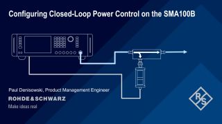
Configuring Closed-Loop Power Control on the SMA100B

Learn how to configure and use closed-loop power control on Rohde & Schwarz analog and vector signal generators based on the example of the R&S®SMA100B .

R&S®SMB100B microwave signal generator explained

Learn about the upgraded features of the R&S®SMB100B microwave signal generator including low SSB, high output power, low harmonics and closed-loop power control.

SMB100B Output power
Ultra high output power

The R&S®SMB100B offers with its ultra high output power option a calibrated one-box solution that saves space and money.

SMB100B SCPI makro recorder
SCPI macro recorder

The built-in SCPI macro recorder with code generator can automatically record all manual settings and create an executable MATLAB® script.

SMB100B UCOR user correction
UCOR (user correction)

With UCOR a frequency response compensated RF signal is available at the new reference plane for the DUT.

Demander des informations

Vous avez des questions ou besoin d'informations supplémentaires ? Remplissez simplement ce formulaire et nous vous recontacterons rapidement.

Marketing de permission

Votre demande a bien été envoyée ! Nous vous contacterons dans les plus brefs délais.
An error is occurred, please try it again later.
Informations générales et conditions d'utilisation du site Web

Manufacturer's recommended retail price (MSRP). The price shown does not include VAT. Prices and offers are only intended for entrepreneurs and not for private end consumers.

You may use the electronic signature via DocuSign to submit your information to enroll with the Rohde & Schwarz Customer Delegated Administration program. DocuSign processes the information provided according to their . The minimum system requirements for using the DocuSign system may change over time. The current system requirements are found

Termes & Conditions du tirage au sort relatif aux 10 ans des oscilloscopes Rohde & Schwarz

1. Le tirage au sort “10 years Rohde & Schwarz oscilloscopes” est organisé par Rohde & Schwarz GmbH & Co. KG, Mühldorfstraße 15, 81671 Munich, Allemagne, Tel. +49 89 41 29 0 (référencé ici par “R&S").

2. Tous les participants peuvent s'inscrire au tirage au sort du 01 janvier 2020 au 31 décembre 2020 avec leur nom, le nom de leur entreprise et leur courriel professionnel.

3. La participation est gratuite et ne dépend pas de l'achat de biens ou de services.

4. Le tirage au sort est uniquement ouvert aux entités juridiques et seules les personnes morales peuvent gagner les prix. Une personne physique n'est pas autorisée à participer en son nom propre et pour son propre compte, mais en tant que représentant d'une entité juridique en remplissant le formulaire de participation au nom et pour le compte de l'entité juridique.

5. Les prix à gagner sont 1 des 10 R&S®RTB2000 au cours de la période allant du 1 janvier 2020 au 31 décembre 2020 :

Prix : 1x oscilloscope numérique R&S®RTB2000

6. Le tirage au sort aura lieu au siège social de Rohde & Schwarz, Muehldorstrasse 15, 81671 Munich. Les gagnants des prix seront informés par courriel sous 5 jours ouvrés.

7. Le représentant autorisé de l'entité juridique devra informer Rohde & Schwarz qu'il accepte le prix. En cas de refus d'acceptation, ou sans aucune réponse dans les deux semaines, un nouveau gagnant sera tiré au sort. Si aucun gagnant ne se manifeste sous quatre semaines, le tirage au sort prend fin et le prix est perdu.

8. Les employés R&S et les membres de leurs familles, ainsi que toute personne participant au processus du tirage au sort et les membres de leurs familles sont exclus du formulaire de participation.

9. Aucun équivalent en argent ou échange de prix n'est autorisé. Les prix ne sont pas transférables. Tous les impôts, les prélèvements, les droits, les taxes et toutes autres charges perçus dans le pays du participant sont à la charge du participant.

10. Les données personnelles seront traitées uniquement dans le cadre de ce tirage au sort et supprimées quatre semaines après celui-ci, sauf indication contraire.

11. Tout participant qui ne respecte pas ces Termes & Conditions peut être disqualifié par Rohde & Schwarz de ce concours. Dans un tel cas, les prix peuvent également être retirés de manière rétroactive. Dans le cas où un prix est retiré de manière rétroactive à cause du non-respect de ces conditions, il devra être retourné par le participant en question à ses frais à l'adresse Rohde & Schwarz mentionnée au point n°1 et un nouveau gagnant sera tiré au sort.

12. Les participants ne peuvent pas réclamer les prix de ce tirage au sort et aucune procédure juridique n'est autorisée à cet égard.

13. Le tirage au sort et toute relation contractuelle qui en découle entre Rohde & Schwarz et le participant respectif sont régis et interprétés conformément aux lois de l'Allemagne, sans aucun recours au conflit de lois. Les tribunaux de Munich, Allemagne, sont seuls compétents en cas de litige émanant directement ou indirectement de la participation à ce concours.

* “fast delivery” inside 7 working days applies to the Rohde & Schwarz in-house procedures from order processing through to available ex-factory to ship.