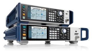
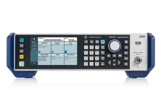
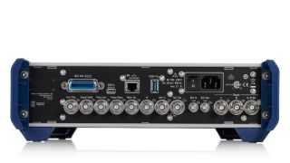
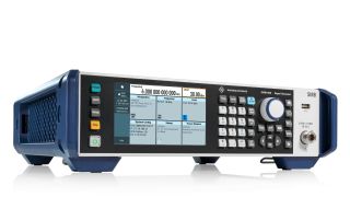
R&S®SMB100B RF and microwave signal generator

R&S®SMB100B RF and microwave signal generator
Abrir Lightbox
R&S®SMB100B RF and microwave signal generator
Abrir Lightbox
R&S®SMB100B RF and microwave signal generator
Abrir Lightbox
R&S®SMB100B RF and microwave signal generator
Abrir Lightbox
R&S®SMB100B RF and microwave signal generator
Abrir Lightbox
R&S®SMB100B RF and microwave signal generator
Abrir Lightbox
R&S®SMB100B RF and microwave signal generator
Abrir Lightbox
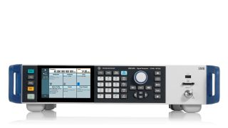
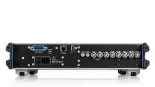
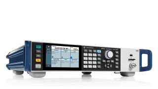
R&S®SMB100B RF and microwave signal generator, hero view R&S®SMB100B RF signal generator, front low R&S®SMB100B RF signal generator, back low R&S®SMB100B RF signal generator, hero view R&S®SMB100B RF and microwave signal generator, front low R&S®SMB100B RF and microwave signal generator, back low R&S®SMB100B RF and microwave signal generator, hero view

Key Facts

  • Frequency range from 8 kHz to 1, 3, 6, 12.75, 20, 31.8 and 40 GHz
  • Outstanding single sideband (SSB) phase noise of < –112 dBc (meas.) at 10 GHz and an offset of 20 kHz
  • Very low wideband noise depending on the frequency range, sometimes well below < –145 dBc (meas.)
  • Highest output power of 34 dBm at 1 GHz, 25 dBm at 20 GHz and 19 dBm at 40 GHz (all is measured)
  • Compact form factor of 2 HU and 3/4 19" width for the R&S®SMB100B RF signal generator (1/3/6 GHz) and 19" width for the R&S®SMB100B microwave signal generator (12.75/20/31.8/40 GHz)

Perfect combination of performance and usability in a compact size

The R&S®SMB100B analog signal generator combines performance and versatility in a small footprint. Outstanding spectral purity and very high output power combined with comprehensive functions and very simple operation characterize the R&S®SMB100B. The R&S®SMB100B analog RF signal generator (3/4 19" width) has a frequency range from 8 kHz to 1, 3 and 6 GHz. The R&S®SMB100B analog microwave signal generator (19" width) has a frequency range from 8 kHz to 12.75, 20, 31.8 and 40 GHz.

Features & benefits

Performance and usability in a compact size:

The R&S®SMB100B has outstanding spectral purity, very high output power and comprehensive functions

The R&S®SMB100B RF and microwave signal generator combines performance and versatility in a small footprint, while offering comprehensive functions and user-friendly operation.

  • Frequency range from 8 kHz to 1, 3, 6, 12.75, 20, 31.8 and 40 GHz
  • Compact form factor of 2 HU and 3/4 19" width for the R&S®SMB100B analog RF signal generator (1/3/6 GHz) and 19" width for the R&S®SMB100B analog microwave signal generator (12.75/20/31.8/40 GHz)
  • Context-sensitive online help provides comprehensive information
  • SCPI macro recorder with a code generator that automatically records manual settings and creates executable MATLAB® scripts

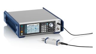
The R&S®SMB100B RF signal generator with connected R&S®NRP power sensor (via USB).
Abrir Lightbox

The R&S®SMB100B RF signal generator with connected R&S®NRP power sensor (via USB).

Perfect for signal quality

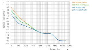
Very low SSB phase noise of < –112 dBc (meas.) at 10 GHz and an offset of 20 kHz

To improve DUTs, signal source quality must be much better than DUT performance. The innovative R&S®SMB100B synthesizer design has very low SSB phase and wideband noise and excellent nonharmonic signal component suppression.

SSB phase noise (1 GHz, 1 Hz BW, meas.)
Abrir Lightbox

SSB phase noise (1 GHz, 1 Hz BW, meas.)

SSB phase noise for the R&S®SMB100B base unit, with the R&S®SMBB-B1 option (OCXO) and the R&S®SMBB-B1H option (high performance OCXO).

Perfect for output power

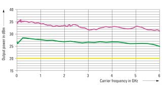
Highest output power of 34 dBm at 1 GHz, 25 dBm at 20 GHz and 19 dBm at 40 GHz (all is measured)

The R&S®SMBB-K31 high output power option for the R&S®SMB100B RF signal generator as well as the R&S®SMBB-K33 high output power option for the R&S®SMB100B (12.75/20 GHz) and the R&S®SMBB-K35 high output power option for the R&S®SMB100B (31.8/40 GHz) are key codes and can be easily activated later on. The R&S®SMB100B RF signal generator lets the high power option be supplemented with the R&S®SMBB-B32 ultra high output power option.
Maximum output power
Abrir Lightbox

Maximum output power

Measured output power for the base unit, with the high power option (R&S®SMBB-K31) and additional ultra-high-power option (R&S®SMBB-B32).;

Perfect for use

The R&S®SMB100B is very user friendly

  • The RF signal generator is easy to operate, can work with a connected R&S®NRP power sensor and emulate legacy instruments. You can also create your own user menu
  • Context-sensitive online help provides comprehensive information
  • SCPI macro recorder with a code generator that automatically records manual settings and creates executable MATLAB® scripts

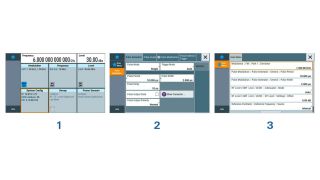
The R&S®SMB100B main screen and user menu
Abrir Lightbox

The R&S®SMB100B main screen and user menu

Sample user menu. Individual parameters can be set directly in this menu.

Variable reference frequency inputs/outputs

The R&S®SMB100B can output (or input) various reference signals. The 1 MHz to 100 MHz variable external reference frequency input (R&S®SMBB-K704 option) allows the R&S®SMB100B to be easily integrated into existing test environments. The received reference frequency can also be sent to a separate reference output (for details see data sheet). Superb phase stability between multiple R&S®SMB100B instruments is possible with the 1 GHz reference frequency input and output option (R&S®SMBB-B3 option).

Variable reference frequency inputs/outputs (rear view of the R&S®SMB100B RF signal generator)
Abrir Lightbox

Variable reference frequency inputs/outputs (rear view of the R&S®SMB100B RF signal generator)

R&S®LegacyPro;

Refresh your T&M equipment

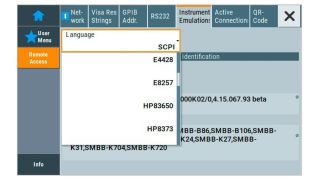
When individual pieces of equipment become obsolete before the entire ATE system, the regular calibration and repair of obsolete equipment is expensive, time consuming and challenging. Replacing obsolete test equipment with equivalent state-of-the-art instruments should be straightforward and require minimal hardware and software changes. R&S®LegacyPro code emulation makes these changes while reducing the workload and eliminating risks.

R&S®LegacyPro code emulation
Abrir Lightbox

R&S®LegacyPro code emulation

Emulation of legacy generators from Rohde & Schwarz and other vendors.

R&S®NRP power sensor connectivity

An R&S®NRP power sensor can be connected to the R&S®SMB100B

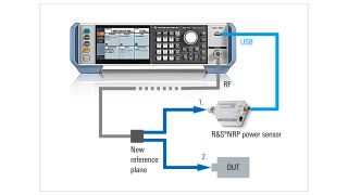
A DUT is rarely connected directly to the generator. There are often cables and other components between the generator and the DUT. This shifts the reference plane from the generator RF output to the DUT. An R&S®NRP power sensor can be connected to the R&S®SMB100B for extremely precise calibration (tenth of a dB) at this new reference plane.

Extremely precise calibration
Abrir Lightbox

Extremely precise calibration

R&S®SMB100B with external devices: R&S®NRP power sensor (via USB); setup for the target power at the new reference plane.

UCOR (user correction)

Compensation of an external frequency response by the R&S®SMB100B with a connected R&S®NRP power sensor

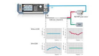
DUTs are often connected to the signal generator via long cables or other frequency-dependent components. Compensating for the frequency response is very important. The R&S®SMB100B has a user correction (UCOR) function. Together with the R&S®NRP power sensor, UCOR values can be automatically determined at the push of a button. A frequency response compensated RF signal is available at the new reference plane for UCOR.

Setup and UCOR function
Abrir Lightbox

Setup and UCOR function

Relative output power display for cables and other components (with their own frequency responses) between the R&S®SMB100B and a DUT.

Closed loop power control (CLPC)

Dynamic compensation of external frequency responses and drifts by the R&S®SMB100B with a connected R&S®NRP power sensor

The dynamic closed loop power control is a standard feature of the R&S®SMB100B. In combination with an R&S®NRP power sensor, the dynamic closed loop power ensures highly accurate and stable input power over time to the DUT regardless of unexpected signal chain losses or gains, unwanted power drifts in the setup or target level changes. The 1GP141 application note describes in great detail the closed loop power control function, the possible signals,suitable signal generator, R&S®NRP power sensors and what needs to be taken into account. Please read the application note before using the closed loop power control for the first time to avoid a possible damage to the DUT.

Available options

Application videos

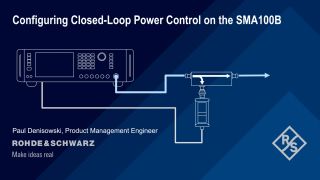
Configuring Closed-Loop Power Control on the SMA100B

Learn how to configure and use closed-loop power control on Rohde & Schwarz analog and vector signal generators based on the example of the R&S®SMA100B .

Solicitar información

¿Tiene preguntas o necesita información adicional? Simplemente complete este formulario y nos pondremos en contacto con usted.

Permiso de marketing

Se ha enviado su solicitud. Nos pondremos en contacto con usted lo antes posible.
An error is occurred, please try it again later.