Written by Peter Busch | March 21, 2022

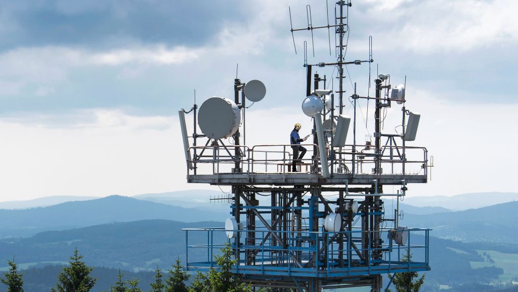
Each new installation must be commissioned and verified to ensure correct network performance and end-user quality of service (QoS) over the 5G network. 5G site testing requires specialist mobile network testing solutions that meet the testing demands of the new RAN architecture, including over-the-air (OTA) connectivity and new KPIs.
The link to the anchor site (usually low-frequency LTE) needs to be checked in parallel for NSA mode. New latency and reliability requirements are becoming reality in campus networks and need to be verified.
Over-the-air testing is moving into the front line of active antenna system (AAS) testing. The beams are produced directly in the antenna, by a varying number of antenna elements. This renders some traditional quality metrics, such as EVM (conducted measurements) unreliable indicators of proper working sites. Instead, beam-centric measurements (SINR/RSRP) measured over the air in front of the cell site are now vital. Deployment will be in the FR1 (sub6 GHz) band and in FR2 (microwave, usually 28 GHz and higher). The LTE anchor cell uses the same antenna or even a different tower, making new test tools and procedures necessary.

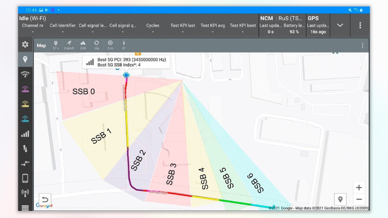
Figure 1: Best SSB (based on RSRP, number of SSB color coded); 5G site with three sectors and 7 beams per sector
5G site testing process
Site acceptance is by no means trivial. Well-defined test procedures and proper test tools create reliable results efficiently. What are the typical required RF tests? How do you group them into different deployment scenarios and itemize the necessary test equipment?
After a 5G site is installed, fundamental cell site performance must be secured, all parameters must be inside a specified range and additional 5G capacity needs to be advertised in the related LTE anchor cells.
Installation / acceptance tasks
- Check VSWR reflections via OSS counters.
- Ensure the PCI and beams are visible in the expected location (SS-RSRP, SS-SINR).
- Conduct power measurements on the allocated LTE anchor cell (RSRP, SINR ..).
- Make sure timing is correct (synchronization relative to UTC)
- Perform functional tests for proper integration of 5G cell into complete network.
- Measure the field strength radiated by the 5G station (EMF).
Troubleshooting steps
- If reflection counters indicate problems, measure reflection / DTF with a cable and antenna tester.
- If beams / PCI are not visible, check and correct the 5G site configuration file. Check cable and antenna.
- If the 5G cell is not used or throughput is too low, check on LTE-SIB 2 whether 5G cell is advertised.
- If SINR is not as expected, check for internal interference (side lobes) and external interference.
- When timing is not within limits, check distributed grandmaster clock timing. Make sure no other delays from broken parts are in the chain generating the RF-signal.
OSS can detect a reflection but does not know if it is originated in the RRH, jumper or antenna. Checking on site reflection / DTF only makes sense when the components are physically separated and the RF-connection between them can be detached.
Complex beam distribution
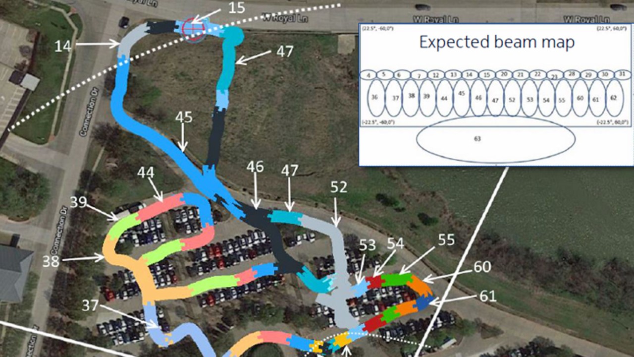
Beam distribution can be very complex in FR2. We have measured cells that distribute 64 beams and can change from one beam to another in just one step.

5G site testing solution
To conduct measurements, we used the Rohde & Schwarz 5G site testing solution R&S®5G STS comprising the receiver / decoder R&S®TSMA6 plus the R&S®TSME30DC downconverter, the handheld troubleshooter QualiPoc Android,, and the R&S®Cable Rider ZPH analyzer.
Cable / antenna tests
Making sure antenna systems are working smoothly is ever more important in 5G. Since 5G deployment started in older LTE sites with dynamic spectrum sharing (DSS), distance-to-fault and reflection tests are crucial to 5G and LTE network performance.

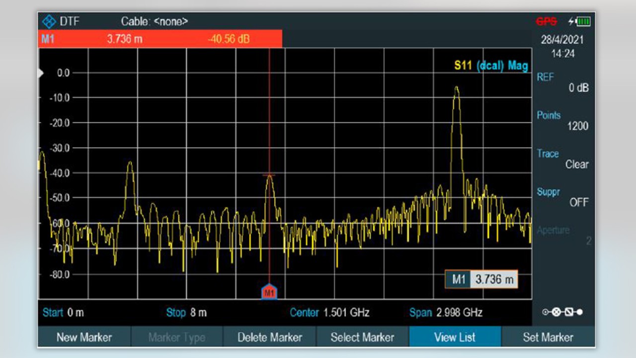
Figure 3: Distance-to-fault measurement with the R&S®Cable Rider ZPH cable and antenna analyzer
Basic RF parameter OTA, frequency domain
A spectrum analyzer detects the initial indications of whether a 5G signal is present in the air. A directional antenna pointed to the sector antenna can be used to measure the occupied bandwidth with the maximum hold function. The SSB section is visible in the middle of the spectrum.

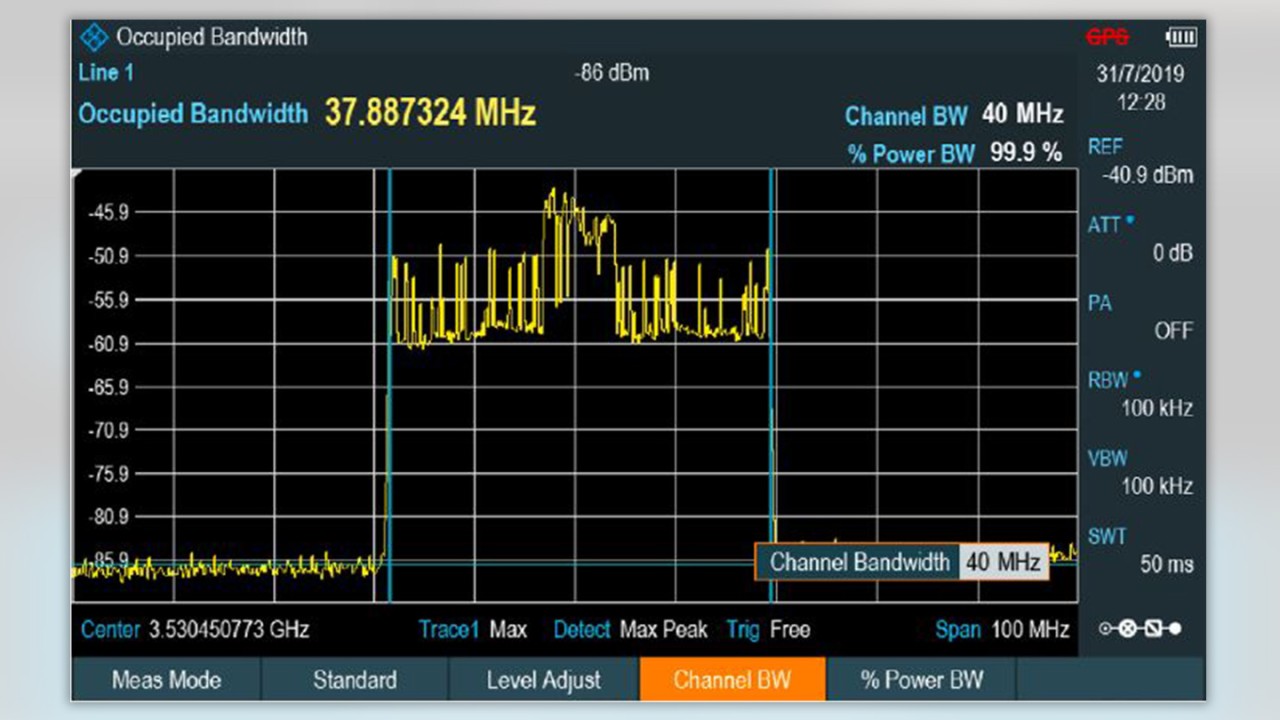
Figure 4: Occupied bandwidth of a 40 MHz 5G NR signal measured over the air with the R&S®Cable Rider ZPH cable and antenna analyzer
Basic RF parameter OTA, time domain
SSBs can be seen in the time domain by going into zero span and using the video trigger. In this example, you can see repeated transmissions of seven beams and some control data. Since this is a non-decoding spectrum measurement, no PCI or SSB indications can be seen.

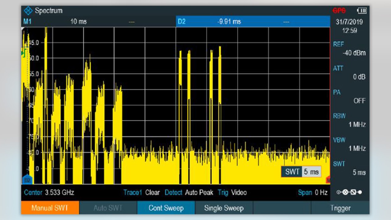
Figure 5: SSB measured over the air in zero span with the R&S®Cable Rider ZPH (additional shorter data/control signals are visible as well)
Demodulation and decoding
Rohde & Schwarz 5G STS adds demodulation and decoding to spectrum measurements. Automated channel detection (ACD) displays all legacy and 5G signals. No channel, frequency or SSB position settings are needed. Further information about the signal content can be obtained by reading relevant broadcasting data (MIB and SIB). Even DSS sites (green rectangular) can be detected (band 1 LTE over 5G at same frequency, within a UMTS gap).

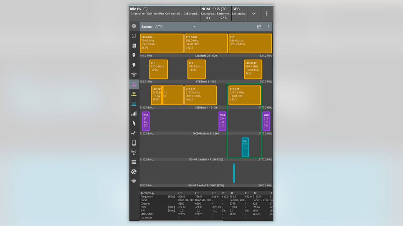
Figure 6: ACD, showing UMTS, LTE and 5G signals in various bands
PCI and beam-centric measurements
The signal of interest can be selected and the availability of beams / PCIs, boundaries of beams/sectors and sidelobes can be checked by filtering via band, PCI, MNC/MCC or SSB.
The results are shown in a Top-N view (highest signal in front) or graph in a value-over-time chart. The example displays two technologies, LTE and parallel 5G.

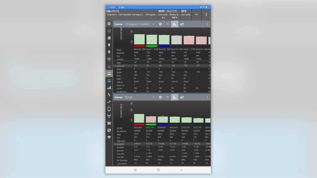
Figure 7: Signal of interest sorted by highest value (RSRP). LTE band 20 + 1 and 5G n1 + n78 traces shown in parallel
Functional tests
Adding a smartphone to the 5G STS allows functional tests such as data uplink or downlink and throughput measurements. Layer 1 parameters and layer 3 signaling can be measured and recorded for further troubleshooting.

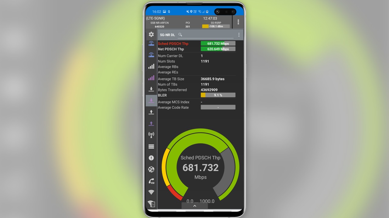
Figure 8: Phone monitor showing 5G parameters
The unique 5G site test solution from Rohde & Schwarz helps operators to overcome the challenges of verifying correct site installation and to troubleshoot sites of 5G networks. The solution offers an efficient method to test layer 1 and layer 3 parameters, new performance KPIs, and the quality experienced (QoE) by end users.
Watch the on-demand Webinar "5G Site Testing including latest real world challenges" and learn more about 5G site acceptance scenarios, KPIs, test techniques, and field measurement results.


